38 - Ring Boxes, страница 19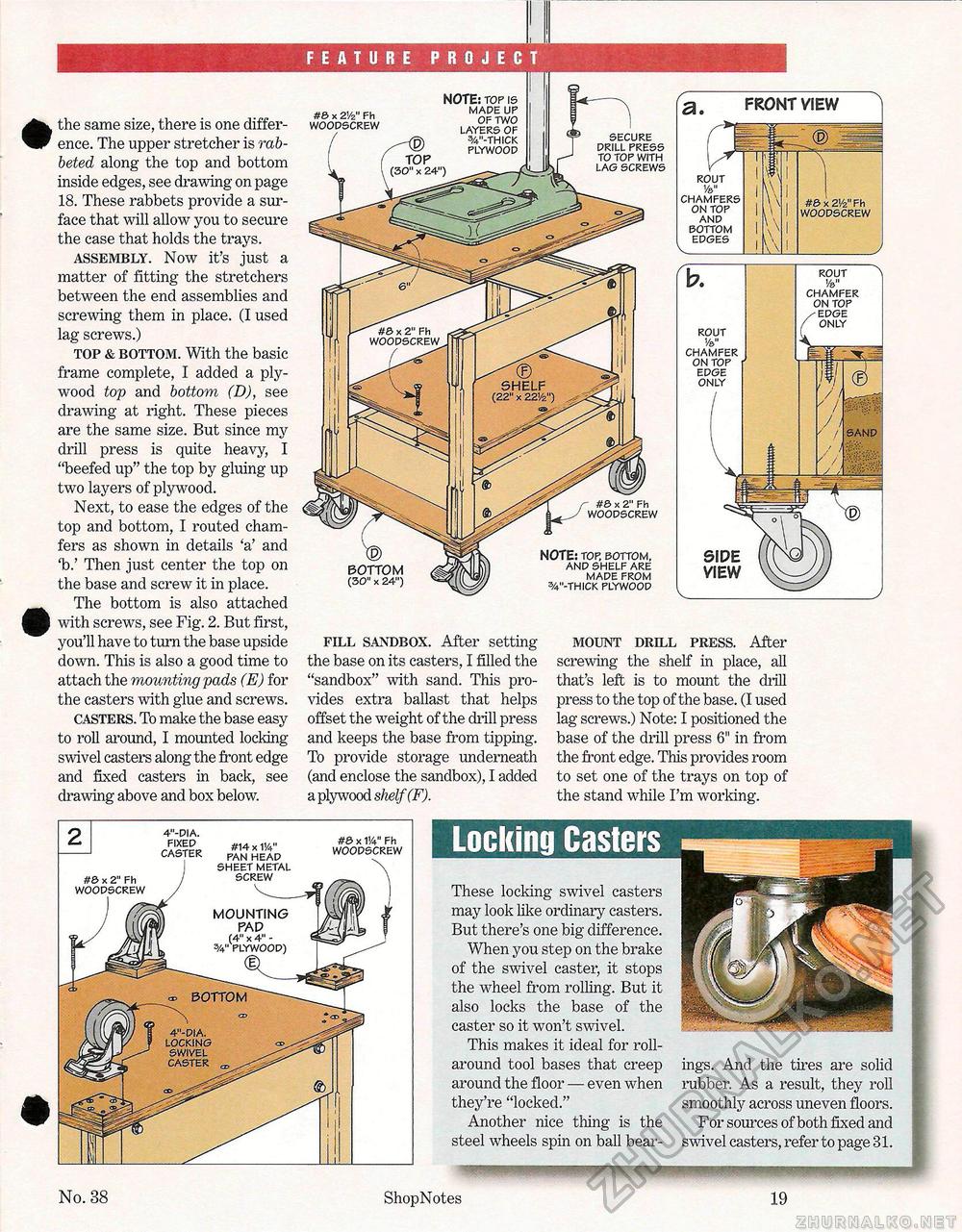
the same size, there is one difference. The upper stretcher is rabbeted along the top and bottom inside edges, see drawing on page 18. These rabbets provide a surface that will allow you to secure the case that holds the trays. assembly. Now it's just a matter of fitting the stretchers between the end assemblies and screwing them in place. (I used lag screws.) top & bottom. With the basic frame complete, I added a plywood top and bottom (D), see drawing at right. These pieces are the same size. But since my drill press is quite heavy, I "beefed up" the top by gluing up two layers of plywood. Next, to ease the edges of the top and bottom, I routed chamfers as shown in details 'a' and 'b.' Then just center the top on the base and screw it in place. The bottom is also attached with screws, see Fig. 2. But first, you'll have to turn the base upside down. This is also a good time to attach the mounting pads (E) for the casters with glue and screws. casters. To make the base easy to roll around, I mounted locking swivel casters along the front edge and fixed casters in back, see drawing above and box below. SECURE DRILL PRESS TO TOP WITH LAG SCREWS #& x 2" Fh WOODSCREW fill sandbox. After setting the base on its casters, I filled the "sandbox" with sand. This provides extra ballast that helps offset the weight of the drill press and keeps the base from tipping. To provide storage underneath (and enclose the sandbox), I added a plywood shelf (F). mount drill press. After screwing the shelf in place, all that's left is to mount the drill press to the top of the base. (I used lag screws.) Note: I positioned the base of the drill press 6" in from the front edge. This provides room to set one of the trays on top of the stand while I'm working. #6 x 21/z" Fh WOODSCREW NOTE: TOP IS MADE UP OF TWO BOTTOM (30" x 24") NOTE: TOP, BOTTOM, AND SHELF ARE MADE FROM 5/4"-THICK PLYWOOD a. FRONT VIEW " ROUT Va" CHAMFERS ON TOP AND BOTTOM EDGES V_ SIDE VIEW v_ ROUT Va" CHAMFER ON TOP /-EDGE x ONLY SAND ROUT Va" CHAMFER ON TOP EDGE ONLY MOUNTING PAP (4" x 4" -PLYWOOD) BOTTOM 4"-DIA. LOCKING SWIVEL CASTER #14 x VA" PAN HEAD SHEET METAL SCREW #& x VA" Fh WOODSCREW #5 x 2" Fh WOODSCREW 4"-DIA. FIXED CASTER These locking swivel casters may look like ordinary casters. But there's one big difference. When you step on the brake of the swivel caster, it stops the wheel from rolling. But it also locks the base of the caster so it won't swivel. This makes it ideal for roll-around tool bases that creep around the floor — even wThen they're "locked." Another nice thing is the steel wheels spin on ball bear ings. And the tires are solid rubber. As a result, they roll smoothly across uneven floors. For sources of both fixed and swivel casters, refer to page 31. No. 38 Shop Notes 19 |


