38 - Ring Boxes, страница 20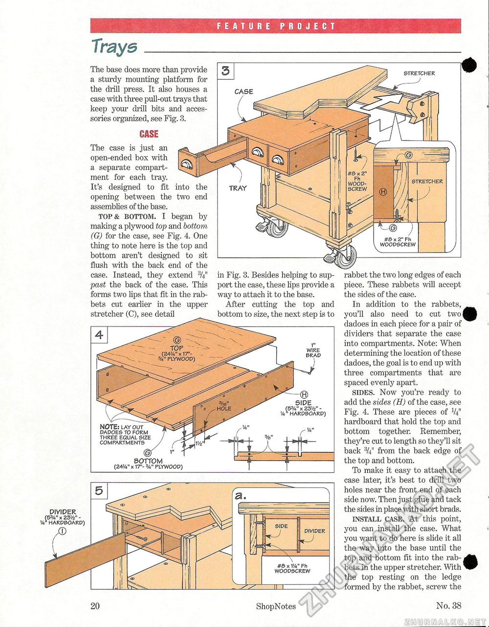
FEATURE PROJECT Traysrabbet the two long edges of each piece. These rabbets will accept the sides of the case. In addition to the rabbets, you'll also need to cut two l dadoes in each piece for a pair of dividers that separate the case into compartments. Note: When determining the location of these dadoes, the goal is to end up with three compartments that are spaced evenly apart. sides. Now you're ready to add the sides (H) of the case, see Fig. 4. These are pieces of V411 hardboard that hold the top and bottom together. Remember, they're cut to length so they'll sit back 'V4 from the back edge of the top and bottom. To make it easy to attach the case later, it's best to drill two holes near the front end of each side now. Then just glue and tack the sides in place with short brads. install case. At this point, you can install the case. What you want to do here is slide it all the way into the base until the top and bottom fit into the rabbets in the upper stretcher. With the top resting on the ledge formed by the rabbet, screw the stretcher The base does more than provide a sturdy mounting platform for the chill press. It also houses a case with three pull-out trays that keep your drill bits and accessories organized, see Fig. 8. into two the end The case is just an open-ended box with a separate compartment for each tray. It's designed to fit opening between the assemblies of the base. top & bottom. I began by making a plywood top and bottom (G) for the case, see Fig. 4. One thing to note here is the top and bottom aren't designed to sit flush with the back end of the case. Instead, they extend past the back of the case. This forms two lips that fit in the rabbets cut earlier in the upper stretcher (C), see detail NOTE; lay out dadoes to form three equal si compartments bottom (24!4" x 17"- 3/4" PLYWOOP) stretcher CASE TRAY in Fig. 3. Besides helping to support the ease, these lips provide a way to attach it to the base. After cutting the top and bottom to size, the next step is to SIDE (5%" x 23Vz" -v' hardboard) #S> x 1!4" Fh woodscrew divider DIVIDER (55/4m x 23Vz" -14* hardboard) side 20 ShopNotes No. 38 |


