43 - Build Your Own Dovetail Jig, страница 28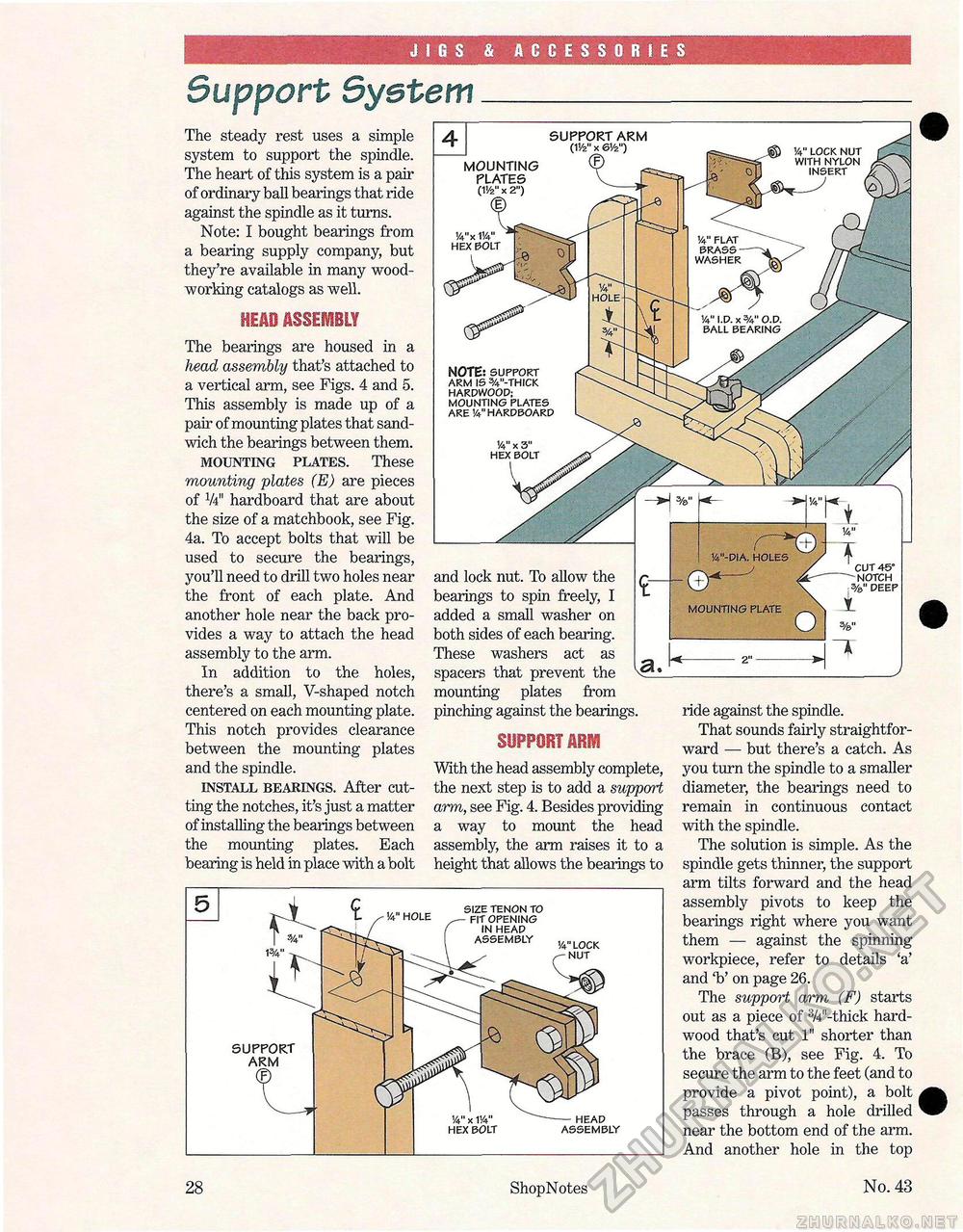
JIGS & ACCESSORIES Support SystemThe steady rest uses a simple system to support the spindle. The heart of this system is a pair of ordinary ball bearings that ride against the spindle as it turns. Note: I bought bearings from a bearing supply company, but they're available in many woodworking catalogs as well. mm ASSEMBLY The bearings are housed in a head assembly that's attached to a vertical arm, see Figs. 4 and 5. This assembly is made up of a pair of mounting plates that sandwich the bearings between them. MOUNTING PLATES. These mounting plates (E) are pieces of V4" hardboard that are about the size of a matchbook, see Fig. 4a. To accept bolts that will be used to secure the bearings, you'll need to drill two holes near the front of each plate. And another hole near the back provides a way to attach the head assembly to the arm. In addition to the holes, there's a small, V-shaped notch centered on each mounting plate. This notch provides clearance between the mounting plates and the spindle. INSTALL BEARINGS. After cutting the notches, it's just a matter of installing the bearings between the mounting plates. Each bearing is held in place with a bolt and lock nut. To allow the bearings to spin freely, I added a small washer on both sides of each bearing. These washers act as spacers that prevent the mounting plates from pinching against the bearings. SUPPORT ABM With the head assembly complete, the next step is to add a support arm, see Fig. 4. Besides providing a way to mount the head assembly, the arm raises it to a height that allows the bearings to 14" hole size tenon to fit opening in heap assembly ,/4„loc|< nut ride against the spindle. That sounds fairly straightforward — but there's a catch. As you turn the spindle to a smaller diameter, the bearings need to remain in continuous contact with the spindle. The solution is simple. As the spindle gets thinner, the support arm tilts forward and the head assembly pivots to keep the bearings right where you want them — against the spinning workpiece, refer to details 'a' and 'b' on page 26. The support arm (F) starts out as a piece of 3/4"-thick hardwood that's cut 1" shorter than the brace (B), see Fig. 4. To secure the arm to the feet (and to provide a pivot point), a bolt passes through a hole drilled near the bottom end of the arm. And another hole in the top 28 ShopNotes No. 43 |


