50 - Table Saw Workstation, страница 9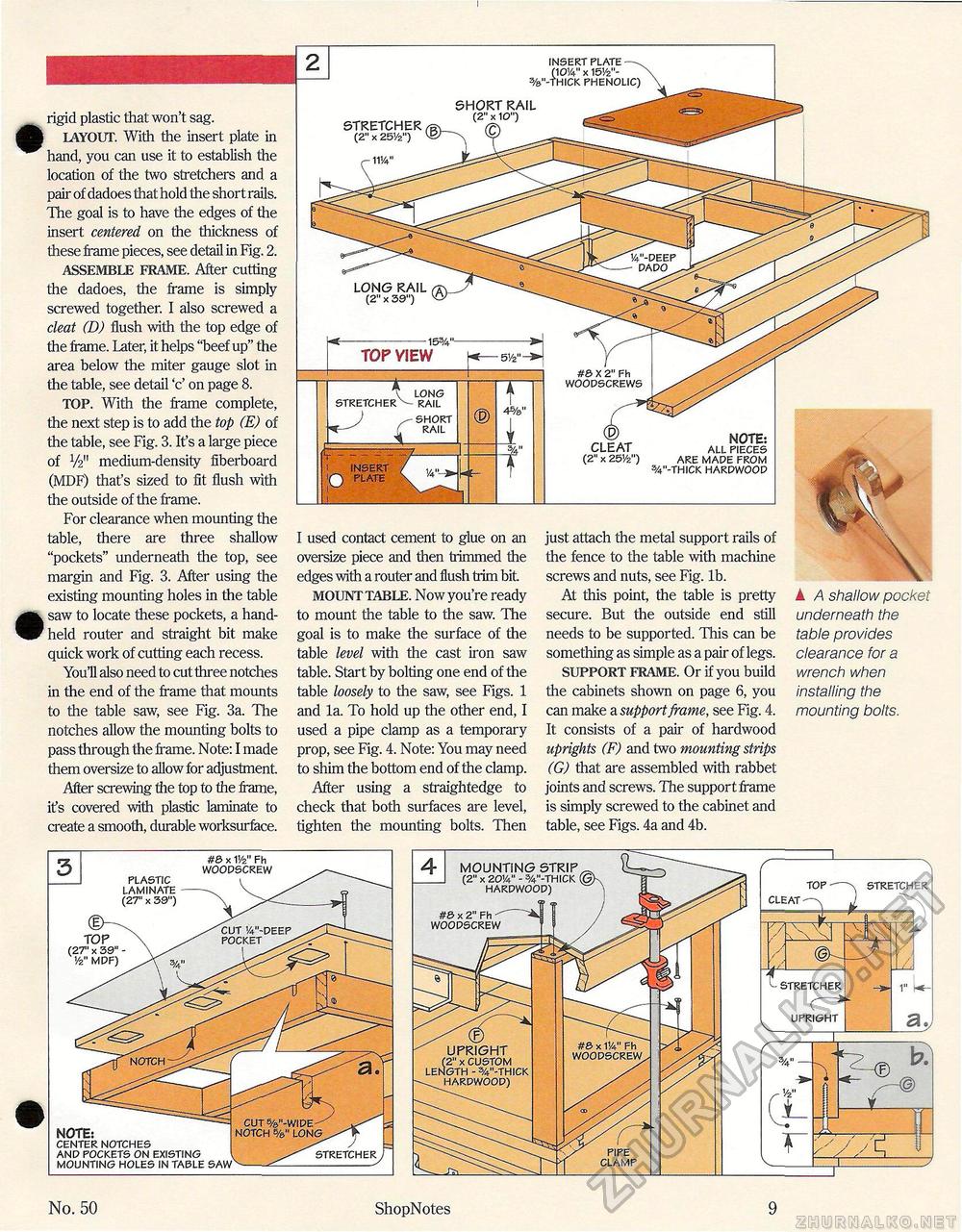
rigid plastic that won't sag. I LAYOUT. With the insert plate in hand, you can use it to establish the location of the two stretchers and a pair of dadoes that hold the short rails. The goal is to have the edges of the insert centered on the thickness of these frame pieces, see detail in Fig. 2. ASSEMBLE FRAME. After cutting the dadoes, the frame is simply screwed together. I also screwed a cleat (D) flush with the top edge of the frame. Later, it helps "beef up" the area below the miter gauge slot in the table, see detail 'c' on page 8. TOP. With the frame complete, the next step is to add the top (E) of the table, see Fig. 3. It's a large piece of i/2" medium-density fiberboard (MDF) that's sized to fit flush with the outside of the frame. For clearance when mounting the table, there are three shallow "pockets" underneath the top, see margin and Fig. 3. After using the existing mounting holes in the table saw to locate these pockets, a handheld router and straight bit make quick work of cutting each recess. YouH also need to cut three notches in the end of the frame that mounts to the table saw, see Fig. 3a. The notches allow the mounting bolts to pass through the frame. Note: I made them oversize to allow for adjustment After screwing the top to the frame, its covered with plastic laminate to create a smooth, durable worksurface. I used contact cement to glue on an oversize piece and then trimmed the edges with a router and flush trim bit MOUNT TABLE. Now you're ready to mount the table to the saw. The goal is to make the surface of the table level with the cast iron saw table. Start by bolting one end of the table loosely to the saw, see Figs. 1 and la. To hold up the other end, I used a pipe clamp as a temporary prop, see Fig. 4. Note: You may need to shim the bottom end of the clamp. After using a straightedge to check that both surfaces are level, tighten the mounting bolts. Then just attach the metal support rails of the fence to the table with machine screws and nuts, see Fig. lb. At this point the table is pretty secure. But the outside end still needs to be supported. This can be something as simple as a pair of legs. SUPPORT FRAME. Or if you build the cabinets shown on page 6, you can make a support frame, see Fig. 4. It consists of a pair of hardwood uprights (F) and two mounting strips (G) that are assembled with rabbet joints and screws. The support frame is simply screwed to the cabinet and table, see Figs. 4a and 4b. k A shallow pocket underneath the table provides clearance for a wrench when installing the mounting bolts. (2" X 20!4" - W-THICK (OK HARDWOOD) x #& x 2" Fh WOODSCREW No. 50 ShopNotes 9 TOP (2T x 39" -'/2" MDF) NOTE: CENTER NOTCHES AND POCKETS ON EXISTING MOUNTING HOLES IN TABLE SAW PLASTIC LAMINATE (27" x 39") #0 x V/2" Fh WOODSCREW |


