50 - Table Saw Workstation, страница 11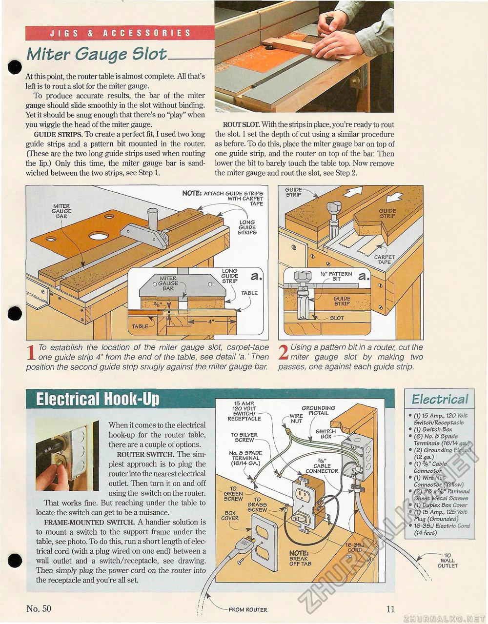
JIGS & ACCESSORIES Miter Gauge Slot_At this point, the router table is almost complete. All that's left is to rout a slot for the miter gauge. To produce accurate results, the bar of the miter gauge should slide smoothly in the slot without binding. Yet it should be snug enough that there's no "play" when you wiggle the head of the miter gauge. GUIDE STRIPS. To create a perfect fit, I used two long guide strips and a pattern bit mounted in the router. (These are the two long guide strips used when routing the lip.) Only this time, the miter gauge bar is sandwiched between the two strips, see Step 1. ROUT SLOT. With the strips in place, you're ready to rout the slot. I set the depth of cut using a similar procedure as before. To do this, place the miter gauge bar on top of one guide strip, and the router on top of the bar. Then lower the bit to barely touch the table top. Now remove the miter gauge and rout the slot, see Step 2. 17o establish the location of the miter gauge slot, carpet-tape one guide strip 4" from the end of the table, see detail 'a.' Then position the second guide strip snugly against the miter gauge bar. 2 Using a pattern bit in a router, cut the miter gauge slot by making two passes, one against each guide strip. LONG s ~UIDE SL TRIP TABLE MITER GAUGE BAR NOTE; ATTACH GUIDE STRIPS WITH CARPET TAPE LONG GUIDE STRIPS Electrical Hook-Up Electrical • (1) 15 Amp., 120 Volt Switch/Receptacle ® (1) Switch Box • (6) No. 3 Spade Terminals (16/14 qa.) ® (2) Grounding Pigtail (12 ga.) • (1) Cable Connector ® (1) Wire Nut Connector (Yellow) e (2) #8 x %" Panhead Sheet Metal Screws • (1) Duplex Box Cover • (1) 15 Amp., 125 Volt Plug (Grounded) • 16-3SJ Electric Cord (14 feet) When it comes to the electrical hook-up for the router table, there are a couple of options. ROUTER SWITCH. The simplest approach is to plug the router into the nearest electrical outlet. Then turn it on and off using the switch on the router. That works fine. But reaching under the table to locate the switch can get to be a nuisance. FRAME-MOUNTED SWITCH. A handier solution is to mount a switch to the support frame under the table, see photo. To do this, run a short length of electrical cord (with a plug wired on one end) between a wall outlet and a switch/receptacle, see drawing. Then simply plug the power cord on the router in; the receptacle and you're all set. FROM ROUTER No. 50 TO WALL OUTLET TO SILVER SCREW TO GREEN SCREW BRASS BOX SCREW COVER 15 AMP. 120 VOLT SWITCH/ RECEPTACLE GROUNDING No. & SPADE TERMINAL |


