93, страница 39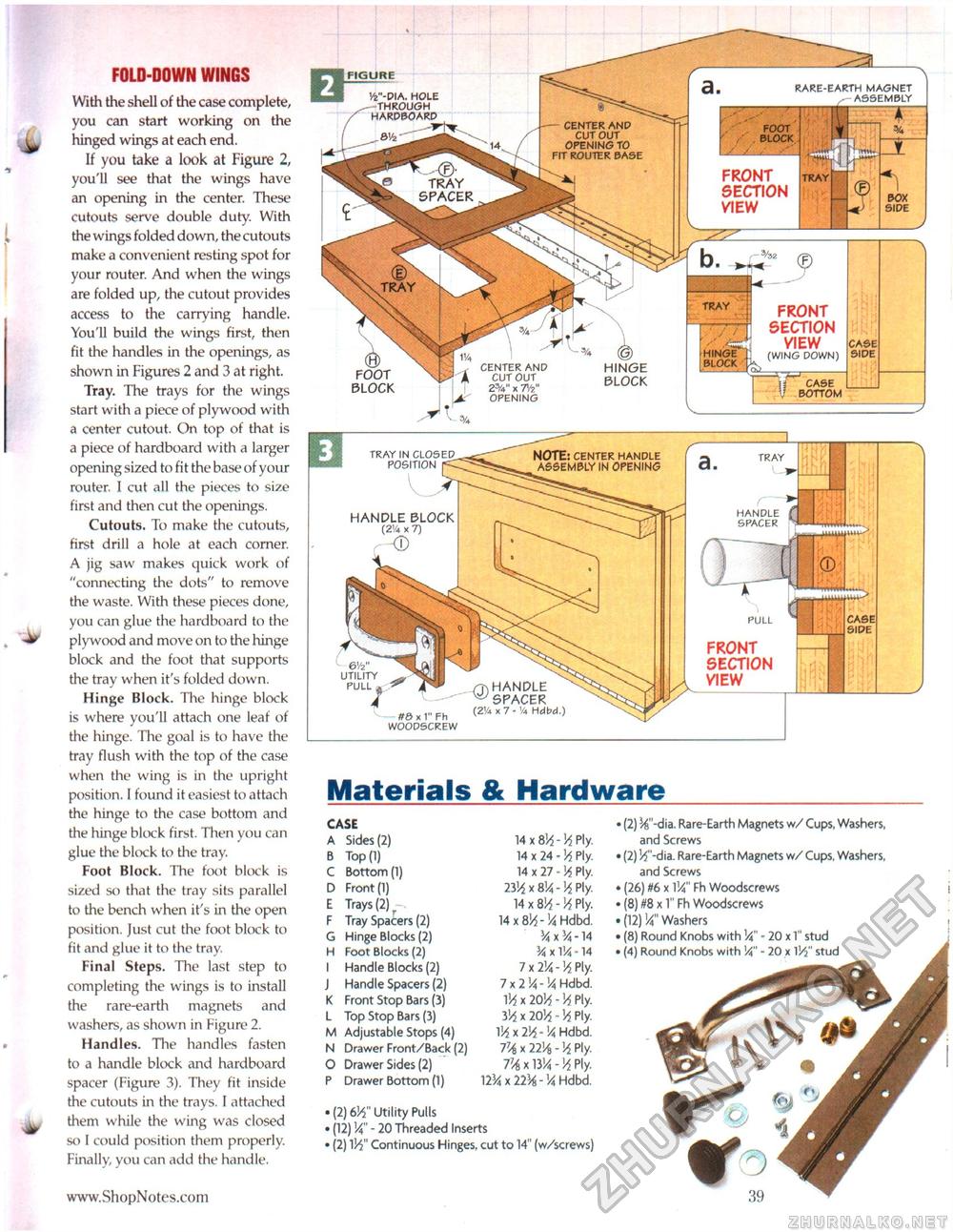
FOLD-DOWN WINGS With the shell of the case complete, you can start working on the ^ hinged wings at each end. If you take a look at Figure 2, you'll see that the wings have an opening in the center. These cutouts serve double duty. With the wings folded down, the cutouts make a convenient resting spot for your router. And when the wings are folded up, the cutout provides access to the carrying handle. You'll build the wings first, then fit the handles in the openings, as shown in Figures 2 and 3 at right. Tray. The trays for the wings start with a piece of plywood with a center cutout. On top of that is a piece of hardboard with a larger opening sized to fit the base of your router. I cut all the pieces to size first and then cut the openings. Cutouts. To make the cutouts, first drill a hole at each corner. A jig saw makes quick work of "connecting the dots" to remove the waste. With these pieces done, you can glue the hardboard to the plywood and move on to the hinge block and the foot that supports the tray when it's folded down. Hinge Block. Tile hinge block is where you'll attach one leaf of the hinge. The goal is to have the tray flush with the top of the case when the wing is in the upright position. I found it easiest to attach the hinge to the case bottom and the hinge block first. Then you can glue the block to the tray. Foot Block. The foot block is sized so that the tray sits parallel to the bench when it's in the open position. Just cut the foot block to fit and glue it to the tray. Final Steps. The last step to completing the wings is to install the rare-earth magnets and washers, as shown in Figure 2. Handles. The handles fasten to a handle block and hardboard spacer (Figure 3). They fit inside the cutouts in the trays. I attached ^ them while the wing was closed so I could position them properly. Finally, you can add the handle. Materials & Hardware
• (2) %"-dia. Rare-Earth Magnets w/ Cups, Washers, and Screws • (2) Vf-dia. Rare-Earth Magnets w/ Cups, Washers, and Screws »(26) #6 x 114" Fh Woodscrews (8) m x 1" Fh Woodscrews (12) Va" Washers (8) Round Knobs with Va - 20 x 1" stud (4) Round Knobs with Va" - 20 x lV$" stud • (2) 6i4" Utility Pulls • (12) Va - 20 Threaded Inserts 1 (2) 1H" Continuous Hinges, cut to 14" (w/screws) • (2) 6i4" Utility Pulls • (12) Va - 20 Threaded Inserts 1 (2) 1H" Continuous Hinges, cut to 14" (w/screws) FIGURE RARE-EARTH MAGNET -— ASSEMBLY Vfe"-DIA. hole —through hardboard — center and cut out opening to fit router base , ' . FOOT ' / , BLOCK / / / FRONT SECTION VIEW TRAY TRAY SPACER TRAY TRAY FRONT SECTION VIEW (WING DOWN) hinge block HINGE BLOCK CENTER AND CUT OUT 23/V' x T/?" OPENING FOOT BLOCK case bottom NOTE: center handle ASSEMBLY IN OPENING TRAY IN CLOSED POSITION |< TRAY HANDLE SPACER HANDLE BLOCK (2'/4 x 7) PULL FRONT SECTION VIEW 6V2" UTILITY PULL j 0) HANDLE ^SPACER (21/4 x 7 -1/4 Hdbd.) #8 x 1" Fh WOODSCREW • (2) %"-dia. Rare-Earth Magnets w/ Cups, Washers, and Screws • (2) Vf-dia. Rare-Earth Magnets w/ Cups, Washers, and Screws »(26) #6 x 114" Fh Woodscrews (8) m x 1" Fh Woodscrews (12) Va" Washers (8) Round Knobs with Va - 20 x 1" stud (4) Round Knobs with Va" - 20 x lV$" stud |
|||||||||||||||||||||||||||||||||||||||||||||||||||


