93, страница 49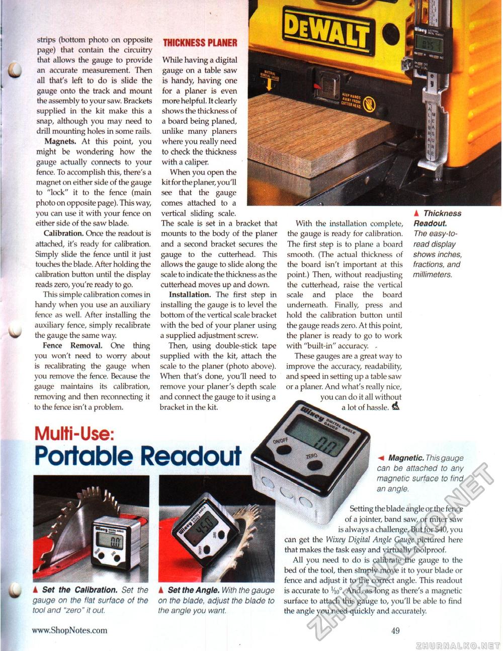
strips (bottom photo on opposite page) that contain the circuitry that allows the gauge to provide an accurate measurement. Then all that's left to do is slide the gauge onto the track and mount the assembly to your saw. Brackets supplied in the kit make this a snap, although you may need to drill mounting holes in some rails. Magnets. At this point, you might be wondering how the gauge actually connects to your fence. To accomplish this, there's a magnet on either side of the gauge to "lock" it to the fence (main photo on opposite page). This way, you can use it with your fence on either side of the saw blade. Calibration. Once the readout is attached, it's ready for calibration. Simply slide the fence until it just touches the blade. After holding the calibration button until the display reads zero, you're ready to go. This simple calibration comes in handy when you use an auxiliary fence as well. After installing the auxiliary fence, simply recalibrate the gauge the same way. Fence Removal, One thing you won't need to worry about is recalibrating the gauge when you remove the fence. Because the gauge maintains its calibration, removing and then reconnecting it to the fence isn't a problem. THICKNESS PLANER While having a digital gauge on a table saw is handy, having one for a planer is even more helpful. It clearly shows the thickness of a board being planed, unlike many planers where you really need to check the thickness with a caliper. When you open the kit for the planer, you'll see that the gauge comes attached to a vertical sliding scale. The scale is set in a bracket that mounts to the body of the planer and a second bracket secures the gauge to the cutterhead. This allows the gauge to slide along the scale to indicate the thickness as the cutterhead moves up and down. Installation. The first step in installing the gauge is to level the bottom of the vertical scale bracket with the bed of your planer using a supplied adjustment screw. Then, using double-stick tape supplied with the kit, attach the scale to the planer (photo above). When that's done, you'll need to remove your planer's depth scale and connect the gauge to it using a bracket in the kit. With the installation complete, the gauge is ready for calibration. The first step is to plane a board smooth. (The actual thickness of the board isn't important at this point.) Then, without readjusting the cutterhead, raise the vertical scale and place the board underneath. Finally, press and hold the calibration button until the gauge reads zero. At this point, the planer is ready to go to work with "built-in" accuracy. - These gauges are a great way to improve the accuracy, readability, and speed in setting up a table saw or a planer. And what's really nice, you can do it all without a lot of hassle. A ▲ Thickness Readout. The easy-to-read display shows inches, fractions, and millimeters. Multi-Use: Portable Readout A Set the Calibration. Set the gauge on the flat surface of the tool and "zero" it out. k Set the Angle. With the gauge on the blade, adjust the blade to the angle you want. m Magnetic. This gauge can be attached to any magnetic surface to find an angle. Setting the blade angle or the fence of a jointer, band saw, or miter saw is always a challenge. But for $40, you can get the Wixey Digital Angle Gauge pictured here that makes the task easy and virtually foolproof. All you need to do is calibrate the gauge to the bed of the tool, then sfmply move it to your blade or fence and adjust it to the correct angle. This readout is accurate to Vio°. And, as long as there's a magnetic surface to attach this gauge to, you'll be able to find the angle you need quickly and accurately. 49 |


