Woodworker's Journal 1980-4-5, страница 16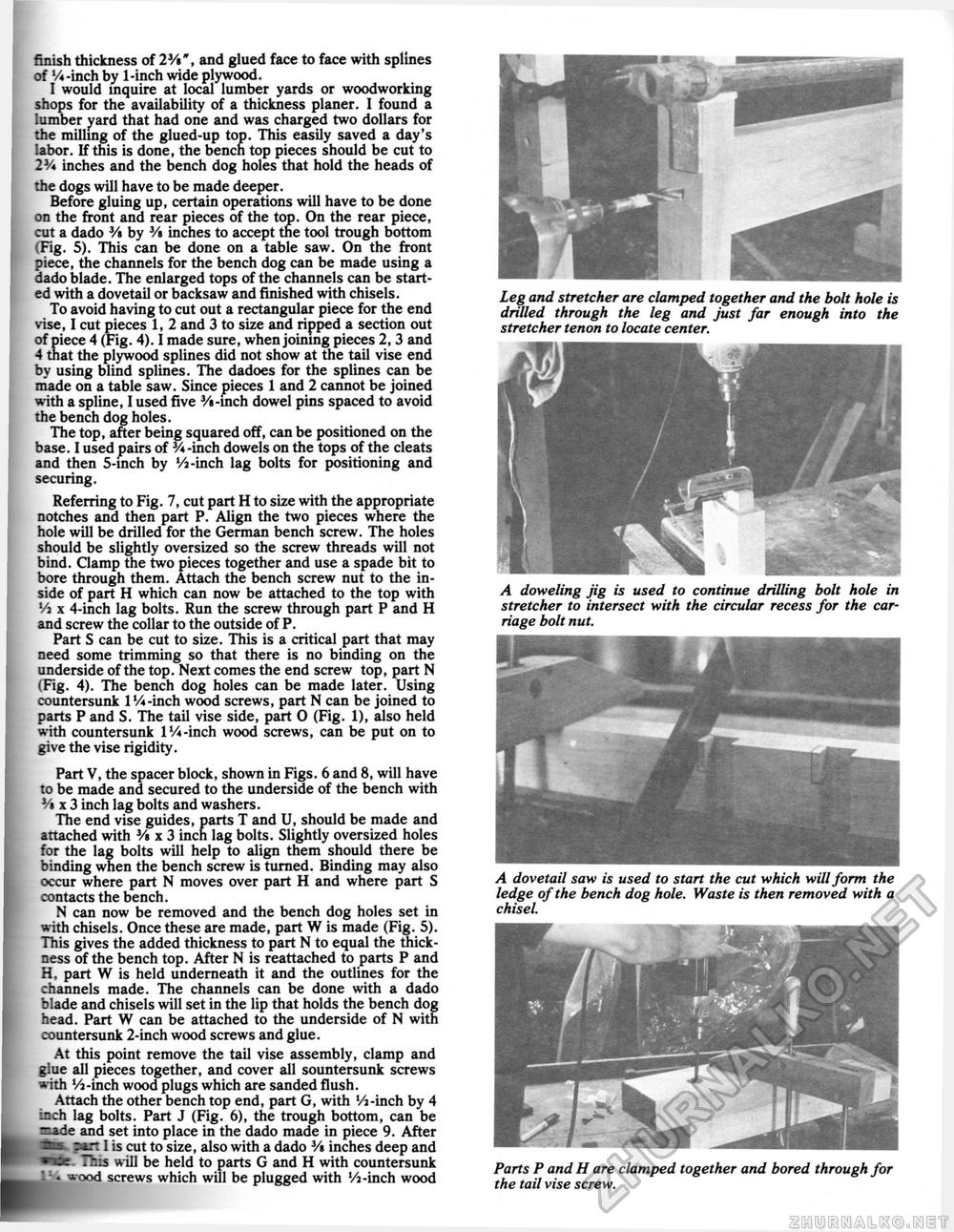
i ! finish thickness of 23/«", and glued face to face with splines of %-inch by 1-inch wide plywood. I would inquire at local lumber yards or woodworking shops for the availability of a thickness planer. I found a lumber yard that had one and was charged two dollars for the milling of the glued-up top. This easily saved a day's labor. If this is done, the bench top pieces should be cut to 2Y* inches and the bench dog holes that hold the heads of the dogs will have to be made deeper. Before gluing up, certain operations will have to be done on the front and rear pieces of the top. On the rear piece, cut a dado 3/» by 3/» inches to accept the tool trough bottom (Fig. 5). This can be done on a table saw. On the front piece, the channels for the bench dog can be made using a dado blade. The enlarged tops of the channels can be started with a dovetail or backsaw and finished with chisels. To avoid having to cut out a rectangular piece for the end vise, I cut pieces 1, 2 and 3 to size and ripped a section out of piece 4 (Fig. 4). I made sure, when joining pieces 2, 3 and 4 that the plywood splines did not show at the tail vise end by using blind splines. The dadoes for the splines can be made on a table saw. Since pieces 1 and 2 cannot be joined with a spline, I used five 3/»-inch dowel pins spaced to avoid the bench dog holes. The top, after being squared off, can be positioned on the base. I used pairs of V* -inch dowels on the tops of the cleats and then 5-inch by Vi-inch lag bolts for positioning and securing. Referring to Fig. 7, cut part H to size with the appropriate notches and then part P. Align the two pieces where the hole will be drilled for the German bench screw. The holes should be slightly oversized so the screw threads will not bind. Clamp the two pieces together and use a spade bit to bore through them. Attach the bench screw nut to the inside of part H which can now be attached to the top with Vi x 4-inch lag bolts. Run the screw through part P and H and screw the collar to the outside of P. Part S can be cut to size. This is a critical part that may need some trimming so that there is no binding on the underside of the top. Next comes the end screw top, part N (Fig. 4). The bench dog holes can be made later. Using countersunk 1 Vi-inch wood screws, part N can be joined to parts P and S. The tail vise side, part O (Fig. 1), also held with countersunk 1 Vi-inch wood screws, can be put on to give the vise rigidity. Part V, the spacer block, shown in Figs. 6 and 8, will have to be made and secured to the underside of the bench with 3/« x 3 inch lag bolts and washers. The end vise guides, parts T and U, should be made and attached with 3/« x 3 inch lag bolts. Slightly oversized holes for the lag bolts will help to align them should there be binding when the bench screw is turned. Binding may also occur where part N moves over part H and where part S contacts the bench. N can now be removed and the bench dog holes set in with chisels. Once these are made, part W is made (Fig. 5). This gives the added thickness to part N to equal the thickness of the bench top. After N is reattached to parts P and H, part W is held underneath it and the outlines for the channels made. The channels can be done with a dado blade and chisels will set in the lip that holds the bench dog head. Part W can be attached to the underside of N with countersunk 2-inch wood screws and glue. At this point remove the tail vise assembly, clamp and glue all pieces together, and cover all sountersunk screws with Vi-inch wood plugs which are sanded flush. Attach the other bench top end, part G, with Vi-inch by 4 •Jich lag bolts. Part J (Fig. 6), the trough bottom, can be =ade and set into place in the dado made in piece 9. After rit I is cut to size, also with a dado 3/» inches deep and This will be held to parts G and H with countersunk • wood screws which will be plugged with Vi-inch wood Leg and stretcher are clamped together and the bolt hole is drilled through the leg and just far enough into the stretcher tenon to locate center. A doweling jig is used to continue drilling bolt hole in stretcher to intersect with the circular recess for the carriage bolt nut. A dovetail saw is used to start the cut which will form the ledge of the bench dog hole. Waste is then removed with a chisel. Parts P and H are clamped together and bored through for the tail vise screw. |


