Woodworker's Journal 1983-7-2, страница 34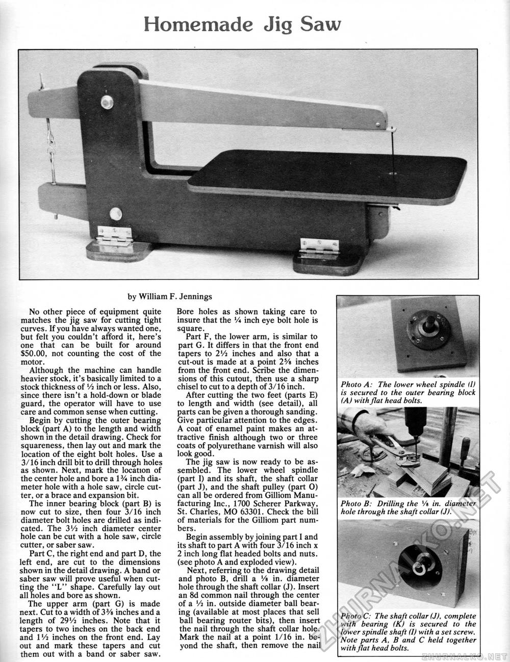
Homemade Jig Saw by William F. Jennings No other piece of equipment quite matches the jig saw for cutting tight curves. If you have always wanted one, but felt you couldn't afford it, here's one that can be built for around $50.00, not counting the cost of the motor. Although the machine can handle heavier stock, it's basically limited to a stock thickness of Vi inch or less. Also, since there isn't a hold-down or blade guard, the operator will have to use care and common sense when cutting. Begin by cutting the outer bearing block (part A) to the length and width shown in the detail drawing. Check for squareness, then lay out and mark the location of the eight bolt holes. Use a 3/16 inch drill bit to drill through holes as shown. Next, mark the location of the center hole and bore a 1V* inch diameter hole with a hole saw, circle cutter, or a brace and expansion bit. The inner bearing block (part B) is now cut to size, then four 3/16 inch diameter bolt holes are drilled as indicated. The 3Vi inch diameter center hole can be cut with a hole saw, circle cutter, or saber saw. Part C, the right end and part D, the left end, are cut to the dimensions shown in the detail drawing. A band or saber saw will prove useful when cutting the "L" shape. Carefully lay out all holes and bore as shown. The upper arm (part G) is made next. Cut to a width of 33/« inches and a length of 29Vi inches. Note that it tapers to two inches on the back end and Wi inches on the front end. Lay out and mark these tapers and cut them out with a band or saber saw. Bore holes as shown taking care to insure that the V* inch eye bolt hole is square. Part F, the lower arm, is similar to part G. It differs in that the front end tapers to 2Vi inches and also that a cut-out is made at a point 2V» inches from the front end. Scribe the dimensions of this cutout, then use a sharp chisel to cut to a depth of 3/16 inch. After cutting the two feet (parts E) to length and width (see detail), all parts can be given a thorough sanding. Give particular attention to the edges. A coat of enamel paint makes an attractive finish although two or three coats of polyurethane varnish will also look good. The jig saw is now ready to be assembled. The lower wheel spindle (part I) and its shaft, the shaft collar (part J), and the shaft pulley (part 0) can all be ordered from Gilliom Manufacturing Inc., 1700 Scherer Parkway, St. Charles, MO 63301. Check the bill of materials for the Gilliom part numbers. Begin assembly by joining part I and its shaft to part A with four 3/16 inch x 2 inch long flat headed bolts and nuts, (see photo A and exploded view). Next, referring to the drawing detail and photo B, drill a Vt in. diameter hole through the shaft collar (J). Insert an 8d common nail through the center of a Vt in. outside diameter ball bearing (available at most places that sell ball bearing router bits), then insert the nail through the shaft collar hole. Mark the nail at a point 1/16 in. beyond the shaft, then remove the nail Photo B: Drilling the '/» in. diameter hole through the shaft collar (J). Photo C: The shaft collar (J), complete with bearing (K) is secured to the lower spindle shaft (I) with a set screw. Note parts A. B and C held together with flat head bolts. Photo A: The lower wheel spindle (I) is secured to the outer bearing block (A) with flat head bolts. |


