Woodworker's Journal 1983-7-2, страница 35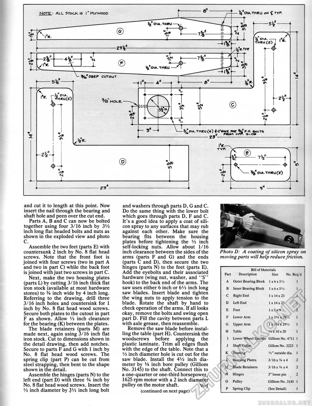
and cut it to length at this point. Now insert the nail through the bearing and shaft hole and peen over the cut end. Parts A, B and C can now be bolted together using four 3/16 inch by 3'/2 inch long flat headed bolts and nuts as shown in the exploded view and photo C. Assemble the two feet (parts E) with countersunk 2 inch by No. 8 flat head screws. Note that the front foot is joined with four screws (two in part A and two in part C) while the back foot is joined with just two screws in part C. Next, make the two housing plates (parts L) by cutting 3/16 inch thick flat iron stock (available at most hardware stores) to V* inch wide by 4 inch long. Referring to the drawing, drill three 3/16 inch holes and countersink for 1 inch by No. 8 flat head wood screws. Secure both plates to the cutout in part F as shown. Allow Vi inch clearance for the bearing (K) between the plates. The blade retainers (parts M) are made next, again using 3/16 inch flat iron stock. Cut to dimensions shown in the detail drawing, then add notches. Secure to parts F and G with 1 inch by No. 8 flat head wood screws. The spring clip (part P) can be cut from steel strapping, then bent to the shape shown in the detail. Assemble the hinges (parts N) to the left end (part D) with three V* inch by No. 8 flat head wood screws. Insert the Vi inch diameter by 3Vi inch long bolt and washers through parts D, G and C. Do the same thing with the lower bolt which goes through parts D, F and C. It's a good idea to apply a coat of silicon spray to any surfaces that may rub against each other. Make sure the bearing fits between the housing plates before tightening the Vi inch self-locking nuts. Allow about 1/16 inch clearance between the sides of the arms (parts F and G) and the ends (parts C and D), then secure the two hinges (parts N) to the feet (parts E). Add the eyebolts and their associated hardware (wing nut, washer, and "S" hook) to the back end of the arms. The saw uses either 6 inch or 6Vi inch long saw blades. Insert blade and tighten the wing nuts to apply tension to the blade. Rotate the shaft by hand to check operation of the arms. If all looks okay, remove the bolts and swing open part D. Fill the cavity between parts L with axle grease, then reassemble. Remove the saw blade before installing the table (part H). Countersink the woodscrews before applying the plastic laminate. Trim all edges flush with the edge of the table. Note that a Vi inch diameter hole is cut out for the saw blade. Install the 4J/2 inch diameter by Vt inch bore pulley (Gilliom No. 3145) to the shaft. Connect this to a one-quarter or one-third horsepower, 1625 rpm motor with a 2 inch diameter pulley on the motor shaft. W\j (continued on next page) moving parts will help reduce friction.
|
||||||||||||||||||||||||||||||||||||||||||||||||||||||||||||||||||||


