Woodworker's Journal 1983-7-5, страница 40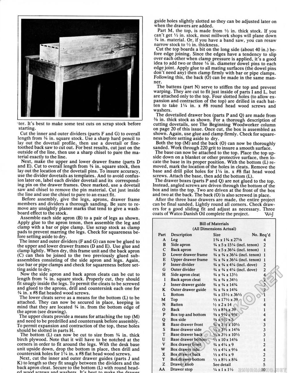
•ter. It's best to make some test cuts on scrap stock before starting. Cut the inner and outer dividers (parts F and G) to overall length from 3A in, square stock. Use a sharp hard pencil to lay out the dovetail profile, then use a dovetail or fine-toothed back saw to cut out. For best results, cut just on the outside of the line, then use a sharp chisel to pare the material exactly to the line. Next, make the upper and lower drawer frame (parts D and E). Cut to overall length from 3A in. square stock, then lay out the location of the dovetail pins. To insure accuracy, use the divider dovetails as templates. And to avoid confusion later on, label each divider dovetail and its corresponding pin on the drawer frames. Once marked, use a dovetail saw and chisel to remove the pin material. Cut just inside the line and use the chisel to pare to an exact fit. Before assembly, give the legs, aprons, drawer frame members and dividers a thorough sanding. Be sure to remove any unsightly planer marks that tend to give a washboard effect to the stock. Assemble each side apron (B) to a pair of legs as shown. Apply glue to the apron tenon, then assemble the leg and clamp with a bar or pipe clamp. Use scrap stock as clamp pads to prevent marring the legs. Check for squareness before setting aside to dry. The inner and outer dividers (F and G) can now be glued to the upper and lower drawer frames (D and E). Use glue and clamp lightly. When dry, this frame unit and the back apron (C) can then be joined to the two previously glued subassemblies consisting of the side apron and legs. Again, use bar or pipe clamps and check for squareness before setting aside to dry. Now the side apron and back apron cleats can be cut to length from 3A in. square stock. Properly cut, they should fit snugly inside the legs. To permit the cleats to be screwed and glued to the aprons, drill and countersink each one for V* in, x #8 flat headed wood screws. The lower cleats serve as a means for the bottom (L) to be attached. They can now be secured in place, keeping in mind that they are located 3A in. from the bottom edge of the apron (see drawing). The upper cleats provide a means for attaching the top (M) and need to be predrilled and countersunk before assembly. To permit expansion and contraction of the top, these holes should be slotted in parts H. The bottom (L) can now be cut to size from 3A in. thick birch plywood. Note that it will have to be notched at the corners in order to fit around the legs. With the desk base unit upside down, drop the bottom in place, then drill and countersink holes for 1Vi in. x #8 flat head wood screws. Next, cut the inner and outer drawer guides (parts J and K) to length so they fit snugly between the dividers and the back apron cleat. Secure to the bottom (L) with round header! urrwt cnrAwc anH \i:achprc it'c lif»ct l-rt ftvQivoc guide holes slightly slotted so they can be adjusted later on when the drawers are added. Part M, the top, is made from Vi in. thick stock. If you can't get Vi in, stock, most millwork shops will plane down in. material. Or, if you have a band saw, you can resaw narrow stock to Vi in. thickness. Cut the top boards a bit on the long side (about 40 in.) before edge joining. Since the edges have a tendency to slip over each other when clamp pressure is applied, it's a good idea to add two or three 'A in. diameter dowel pins to each edge joint. Apply glue to all mating surfaces (the dowel pins don't need any) then clamp firmly with bar or pipe clamps. Following this, the back (O) can be made in the same manner. The battens (part N) serve to stiffen the top and prevent warping. They are cut to fit just inside of parts I and L, but are attached only to the top. Four slotted holes (to allow expansion and contraction of the top) are drilled in each batten to take I 'A in. x #8 round head wood screws and washers. The dovetailed drawer box (parts P and Q) are made from % in. thick stock as shown. For a thorough description of cutting dovetails, see The Beginning Woodworker column on page 20 of this issue. Once cut, the box is assembled as shown. Again, use glue and clamp firmly. Check for squareness before setting aside to dry. Both the top (M) and the back (0) can now be thoroughly sanded. Work through 220 grit to insure a smooth surface. The base can now be attached to the top. Place the top upside down on a blanket or other protective surface, then locate the base in its proper position. With the bottom (L) removed, mark the location of the holes in cleats. Remove the base and drill pilot holes for VA in. x #8 flat head wood screws. Attach the base, then add the bottom (L). The drawer boxes (parts P and Q) are not glued to the top. Instead, angled screws are driven through the bottom of the box and into the top. Two are driven at the front of the box and two at the back. The back (0) is also screwed in place. After the three base drawers are made, the entire project can be final sanded. Lightly round all corners. Check drawers for a good sliding fit and adjust as necessary. Three coats of Watco Danish Oil complete the project. ' \\<\j Bill of Materials (AH Dimensions Actual) Bill of Materials (AH Dimensions Actual)
|
||||||||||||||||||||||||||||||||||||||||||||||||||||||||||||||||||||||||||||||||||||||||||||||||||||||||||||||||


