Woodworker's Journal 1983-7-5, страница 43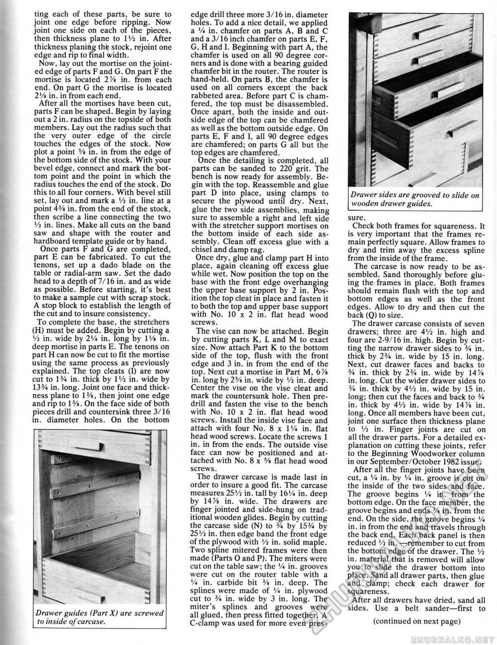
ting each of these parts, be sure to joint one edge before ripping. Now joint one side on each of the pieces, then thickness plane to IVt in. After thickness planing thfe stock, rejoint one edge and rip to final width. Now, lay out the mortise on the jointed edge of parts F and G. On part F the mortise is located 2V» in. from each end. On part G the mortise is located 2Vi in. in from each end. After all the mortises have been cut, parts F can be shaped. Begin by laying out a 2 in. radius on the topside of both members. Lay out the radius such that the very outer edge of the circle touches the edges of the stock. Now plot a point V» in. in from the edge of the bottom side of the stock. With your bevel edge, connect and mark the bottom point and the point in which the radius touches the end of the stock. Do this to ail four corners. With bevel still set, lay out and mark a Vi in. line at a point 4Vt in. from the end of the stock, then scribe a line connecting the two '/a in. lines. Make all cuts on the band saw and shape with the router and hardboard template guide or by hand. Once parts F and G are completed, part E can be fabricated. To cut the tenons, set up a dado blade on the table or radial-arm saw, Set the dado head to a depth of 7/16 in. and as wide as possible. Before starting, it*s best to make a sample cut with scrap stock. A stop block to establish the length of the cut and to insure consistency. To complete the base, the stretchers (H) must be added. Begin by cutting a '/] in. wide by 2lA in. long by IVt in. deep mortise in parts E. The tenons on part H can now be cut to fit the mortise using the same process as previously explained. The top cleats (I) are now cut to 1V* in. thick by 1 Vj in. wide by 133A in. long. Joint one face and thickness plane to I1/*, then joint one edge and rip to IVt. On the face side of both pieces drill and countersink three 3/16 in. diameter holes. On the bottom Drawer guides <Part X) are screwed to inside of carcase. edge drill three more 3/ 1 6 in. diameter holes. To add a nice detail, we applied a V* in. chamfer on parts A, B and C and a 3/16 inch chamfer on parts E, F, G, H and I. Beginning with part A, the chamfer is used on all 90 degree corners and is done with a bearing guided chamfer bit in the router. The router is hand-held. On parts B, the chamfer is used on all corners except the back rabbeted area. Before part C is chamfered. the top must be disassembled. Once apart, both the inside and outside edge of the top can be chamfered as well as the bottom outside edge. On parts E, F and 1. all 90 degree edges are chamfered; on parts G all but the top edges are chamfered. Once the detailing is completed, alt parts can be sanded to 220 grit. The bench is now ready for assembly. Begin with the top. Reassemble and glue part D into place, using clamps to secure the plywood until dry. Next, glue the two side assemblies, making sure to assemble a right and left side with the stretcher support mortises on the bottom inside of each side assembly. Clean off excess glue with a chisel and damp rag. Once dry, glue and clamp part H into place, again cleaning off excess glue while wet. Now position the top on the base with the front edge overhanging the upper base support by 2 in. Position the top cleat in place and fasten it to both the top and upper base support with No. 10 x 2 in. flat head wood screws. The vise can now be attached. Begin by cutting parts K, L and M to exact si2e. Now attach Part K. to the bottom side of the top, flush with the front edge and 3 in. in from the end of the top. Next cut a mortise in Part M, 6'/i in. long by 2s/i in. wide by '/a in, deep. Center the vise on the vise cleat and mark the countersunk hole. Then pre-drill and fasten the vise to the bench with No. 10 x 2 in. flat head wood screws. Install the inside vise face and attach with four No. 8 x 1% in. flat head wood screws. Locate the screws 1 in. in from the ends. The outside vise face can now be positioned and attached with No. 8 x Vt flat head wood screws. The drawer carcase is made last in order to insure a good fit. The carcase measures 25'/i in. tall by 16V* in, deep by 14 Vt in, wide. The drawers are finger jointed and side-hung on traditional wooden glides. Begin by cutting the carcase side (N) to 3A by'l53/i by 25Vi in. then edge band the front edge of the plywood with '/a in. solid maple. Two spline mitered frames were then made (Parts O and P). The miters were cut on the table saw; the '/i in. grooves were cut on the router table with a V* in. carbide bit V» in. deep. The splines were made of Vi in. plywood cut to 3A in. wide by 3 in. long. The miter's splines and grooves were all glued, then press fitted together. A C-clamp was used for more even pres- Drawer sides are grooved to slide on wooden drawer guides. sure. Check both frames for squareness. It is very important that the frames remain perfectly square. Allow frames to dry and trim away the excess spline from the inside of the frame. The carcase is now ready to be assembled. Sand thoroughly before gluing the frames in place. Both frames should remain flush with the top and bottom edges as well as the front edges. Allow to dry and then cut the back (0) to size. The drawer carcase consists of seven drawers; three are 4'/a in. high and four are 2-9/16 in. high. Begin by cutting the narrow drawer sides to 3A in. thick by 2V* in. wide by 15 in. long. Next, cut drawer faces and backs to 3A in. thick by 23A in. wide by 14% in. long. Cut the wider drawer sides to y* in. thick by 4l/i in. wide by 15 in. long; then cut the faces and back to 3A in. thick by 4'A in. wide by 14Vi in. long. Once alt members have been cut, joint one surface then thickness plane to Vi in. Finger joints are cut on alt the drawer parts. For a detailed explanation on cutting these joints, refer to the Beginning Woodworker column in our September/October 1982 issue. After ail the finger joints have been cut, a 'A in. by Y* in. groove is cut on the inside of the two sides and face. The groove begins V* in. from the bottom edge. On the face member, the groove begins and ends V* in. from the end. On the side, the groove begins Vi in. in from the end and travels through the back end. Each back pane! is then reduced '/i in. —remember to cut from the bottom edge of the drawer. The '/a in, material that is removed will allow you to slide the drawer bottom into place. Sand all drawer parts, then glue and clamp; check each drawer for squareness. After ali drawers have dried, sand all sides. Use a belt sander—first to (continued on next page) |


