Woodworker's Journal 1983-7-5, страница 42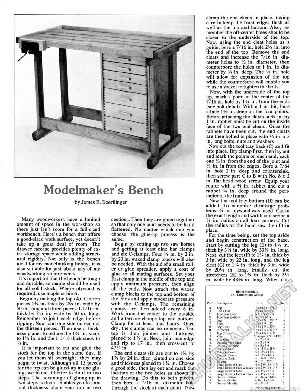
Modelmaker's Bench by James E. Doerflinger Many woodworkers have a limited amount of space in the workshop so there just isn't room for a full-sized workbench. Here's a bench that offers a good-sized work surface, yet doesn't take up a great deal of room. The drawer carcase provides plenty of extra storage space while adding structural rigidity. Not only is the bench ideal for my modelmaking hobby, it is also suitable for just about any of my woodworking requirements. It's important that the bench be tough and durable, so maple should be used for all solid stock. Where plywood is required, use maple or birch. Begin by making the top (A). Cut ten pieces IV* in. thick by 2V* in. wide by 50 in. long and three pieces 1-1/16 in, thick by 2V* in. wide by SO in. long. Remember to joint each edge before ripping. Now joint one side on each of the thirteen pieces. Then use a thickness planer to reduce the IV* in. stock to I Vi in. and the 1-1/16 thick stock to 7A in. It is important to cut and glue the stock for the top in the same day. If you let them sit overnight, they may begin to twist. Although all 13 pieces for the top can be glued-up in one gluing. we found it better to do it in two steps. The advantage of gluing-up in two steps is that it enables you to joint and thickness plane your top in two sections. Then they are glued together so that only one joint needs to be hand flattened. No matter which one you choose, the glue-up process is the same. Begin by setting up two saw horses and getting at least nine bar clamps and six C-clamps. Four V* in. by 2 in. by 20 in. waxed clamp blocks will also be needed. With the aid of a small roller or glue spreader, apply a coat of glue to all mating surfaces. Set your First clamp in the middle of the top and apply minimum pressure, then align all the ends. Now attach the waxed clamp blocks to the top and bottom of the ends and apply moderate pressure with the C-clamps. The remaining clamps are then added every 6 in. Work from the center to the outside and alternate clamps top and bottom. Clamp for at least four hours. Once dry, the clamps can be removed. The top is then jointed and thickness planed to 1 V» in. Next, joint one edge and rip to 17 in., then cross-cut to 47% in. The end cleats (B) are cut to IV* by 1 V% by 24 in. then jointed on one side and thickness planed to 1Y» in. Choose a good side, then iay out and mark the location of the two holes as shown in the drawing. Do this to both pieces, then bore a 7/16 in. diameter hole through the stock at each point. Now clamp the end cleats in place, taking care to keep the front edges flush as well as the top and bottom. Also, remember the off-center holes should be closer to the underside of the top. Now, using the end cleat holes as a guide, bore a 7/16 in. hole 2Vi in. into the end of the top. Remove the end cleats and increase the 7/16 in, diameter holes to Vi in. diameter, then counterbore the holes to 1 in. in diameter by V* in. deep. The Va in. hole will allow for expansion of the top while the counterbore will enable you to use a socket to tighten the bolts, Now, with the underside of the top up, mark a point in the center of the 7/16 in, hole by IV* in. from the ends (see bolt detail). With a 1 in. bit, bore a hole l'/j in. deep on the four points. Before attaching the cleats, a V* in. by 1 in, rabbet must be cut on the inside face of the two end cleats. Once the rabbets have been cut, the end cleats are then bolted in place with V> in. x 3 in. long bolts, nuts and washers. Now cut the tool tray back (C) and fit into place. Dry clamp first, then lay out and mark the points on each end, each one Vi in. from the end of the joint and Vi in. in from the edges. Bore a 7/64 in. hole 2 in. deep and countersink, then screw part C to B with No. 8x2 in. flat head wood screw. Equip your router with a V» in. rabbet and cut a rabbet V* in. deep around the perimeter of the frame. Now the tool tray bottom (D) can be added. To minimize shrinkage problems, V* in. plywood was used. Cut to the exact length and width and scribe a 3/a in, radius on all four corners. Cut the radius on the band saw then fit in place. For the time being, set the top aside and begin construction of the base. Start by cutting the leg (E) to IV* in. thick by 3Vs in. wide by 30V» in. long. Next, cut the feet (F) to IV* in. thick by 3 in. wide by 22 in. long, and the leg cleat (G) to IV* in. thick by 3 in. wide by 20Vj in. long. Finally, cut the stretchers (H) to IV* in. thick by 3Vi in. wide by 43s/« in. long. When cut- Bil ill Materials I All Dimensions Actual Bil ill Materials I All Dimensions Actual
° including tenons ° including tenons |
||||||||||||||||||||||||||||||||||||||||||||||||||||||||||||||||||||||||||||||||||||||||||||||||||||||||


