Woodworker's Journal 1983-7-5, страница 61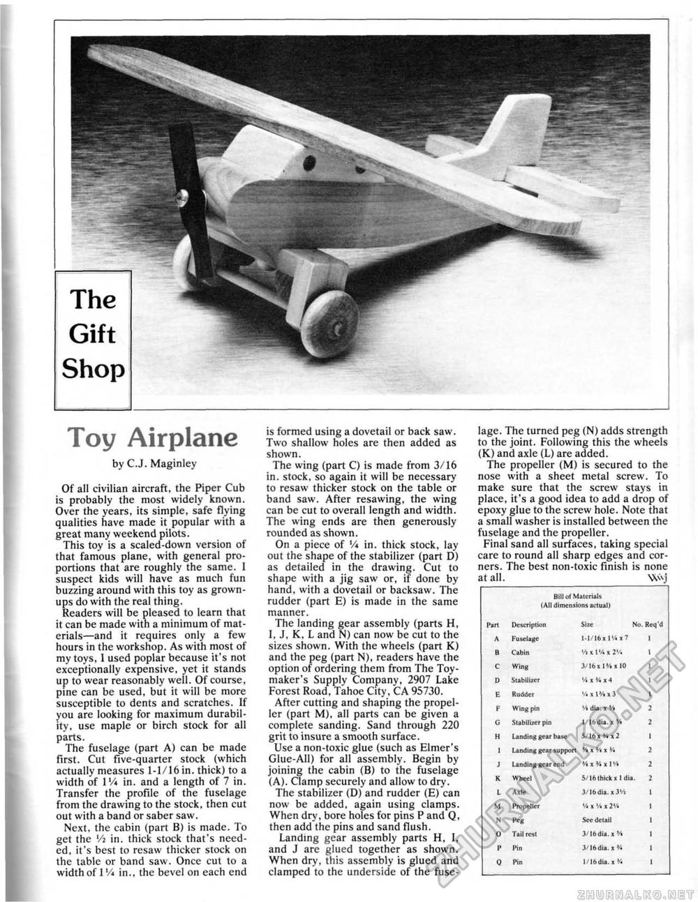
Toy Airplane by CJ. Maginley Of all civilian aircraft, the Piper Cub is probably the most widely known. Over the years, its simple, safe flying qualities have made it popuiar with a great many weekend pilots. This toy is a scaled-down version of that famous plane, with general proportions that are roughly the same. I suspect kids will have as much fun buzzing around with this toy as grownups do with the real thing. Readers will be pleased to learn that it can be made with a minimum of materials—and it requires only a few hours in the workshop. As with most of my toys, 1 used poplar because it's not exceptionally expensive, yet it stands up to wear reasonably well. Of course, pine can be used, but it will be more susceptible to dents and scratches. If you are looking for maximum durability, use maple or birch stock for all parts. The fuselage (part A) can be made first. Cut five-quarter stock (which actually measures 1-1/16 in. thick) to a width of I'A in. and a length of 7 in. Transfer the profile of the fuselage from the drawing to the stock, then cut out with a band or saber saw. Next, the cabin (part B) is made. To get the lA in. thick stock that's needed, it's best to resaw thicker stock on the table or band saw. Once cut to a width of I Vi in., the bevel on each end is formed using a dovetail or back saw. Two shallow holes are then added as shown. The wing (part C) is made from 3/16 in. stock, so again it will be necessary to resaw thicker stock on the table or band saw. After resawing, the wing can be cut to overall length and width. The wing ends are then generously rounded as shown. On a piece of 'A in. thick stock, lay out the shape of the stabilizer (part D) as detailed in the drawing. Cut to shape with a jig saw or, if done by hand, with a dovetail or backsaw. The rudder (part E) is made in the same manner. The landing gear assembly (parts H, 1. J, K, L and N) can now be cut to the sizes shown. With the wheels (part K) and the peg (part N), readers have the option of ordering them from The Toy-maker's Supply Company, 2907 Lake Forest Road, Tahoe City, CA 95730. After cutting and shaping the propeller (part M), all parts can be given a complete sanding. Sand through 220 grit to insure a smooth surface. Use a non-toxic glue (such as Elmer's Glue-All) for all assembly. Begin by joining the cabin (B) to the fuselage (A). Clamp securely and allow to dry. The stabilizer (D) and rudder (E) can now be added, again using clamps. When dry, bore holes for pins P and Q, then add the pins and sand flush. Landing gear assembly parts H, I, and J are glued together as shown. When dry, this assembly is glued and clamped to the underside of the fuse lage. The turned peg (N) adds strength to the joint. Following this the wheels (K) and axle (L) are added. The propeller (M> is secured to the nose with a sheet metal screw. To make sure that the screw stays in place, it's a good idea to add a drop of epoxy glue to the screw hole. Note that a small washer is installed between the fuselage and the propeller. Final sand all surfaces, taking special care to round all sharp edges and corners. The best non-toxic finish is none at all. \V\j
|
||||||||||||||||||||||||||||||||||||||||||||||||||||||||||||||||||||||||||||


