Woodworker's Journal 1983-7-6, страница 41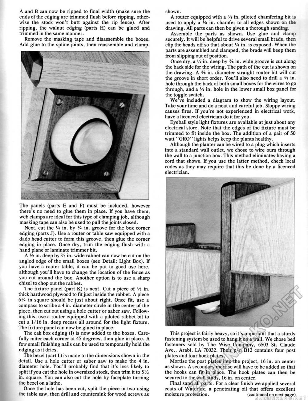
A and B can now be ripped to final width (make sure the ends of the edging are trimmed flush before ripping, otherwise the stock won't butt against the rip fence). After ripping, the walnut edging (parts H) can be glued and trimmed in the same manner. Remove the masking tape and disassemble the boxes. Add glue to the spline joints, then reassemble and clamp. The panels (parts E and F) must be included, however there's no need to glue them in place. If you have them, web clamps are ideal for this type of clamping job, although masking tape can also be used to pull the joints closed. Next, cut the '/« in. by V* in. groove for the box corner edging (parts J). Use a router or table saw equipped with a dado head cutter to form this groove, then glue the corner edging in place. Once dry, trim the edging flush with a hand plane or laminate trimmer bit. A Vi in. deep by V% in. wide rabbet can now be cut on the angled edge of the small boxes (see Detail: Light Box). If you have a router table, it can be put to good use here, although you'll have to change the location of the fence as you cut around the box. Another option is to use a sharp chisel to chop out the rabbet. The fixture panel (part K) is next. Cut a piece of Vi in, thick hardwood plywood to fit just inside the rabbet. A piece 6Vi in square should be just about right. Once fit. use a compass to scribe a 4 in. diameter circle in the center of the piece, then cut out using a hole cutter or saber saw, Following this, use a router equipped with a piloted rabbet bit to cut a 1/16 in. deep recess all around for the light fixture. The fixture panel can now be glued in place. The oak box edging (I) is now added to the boxes. Carefully miter each corner at 45 degrees, then glue in place. A few small finishing nails can be used to temporarily hold the edging as it dries. The bezel (part L) is made to the dimensions shown in the detail. Use a hole cutter or saber saw to make the 4 in, diameter hole. You'll probably find that it's less likely to split if you cut the hole in oversized stock, then trim it to 5'/i in, square. You can also cut the hole by faceplate turning the bezel on a lathe. Once the hole has been cut, split the piece in two using the table saw, then drill and countersink for wood screws as shown. A router equipped with a V* in. piloted chamfering bit is used to apply a 3/s in. chamfer to all edges shown on the drawing. All parts can then be given a thorough sanding. Assemble the parts as shown. Use glue and clamp securely. It will be helpful to drive several small brads, then clip the heads off so that about '/, in, is exposed. When the parts are assembled and clamped, the brads will keep them from slipping out of position. Once dry, a Vi in. deep by Vt in. wide groove is cut along the back side for the wiring. The path of the cut is shown on the drawing. A Vt in. diameter straight router bit will cut the groove in short order. You'll also need to drill a Vt in. hole through the back of both small boxes for the wires to go through, and a Vt in. hole in the lower small box panel for the toggle switch. We've included a diagram to show the wiring layout. Take your time and do a neat and careful job. Sloppy wiring causes fires. If you're not experienced in electrical work, have a licenced electrician do it for you. Eyeball style light fixtures are available at just about any electrical store. Note that the edges of the fixture must be trimmed to fit inside the box. The addition of a pair of 50 watt "GRO" lights helps keep the plants healthy. Although the planter can be wired to a plug which inserts into a standard wall outlet, we chose to wire ours through the wall to a junction box. This method eliminates having a cord that shows. If you use the latter method, check local codes as they may require that this be done by a licenced electrician. This project is fairly heavy, so it's important that a sturdy fastening system be used to hang it on a wall. We chose bed fasteners sold by The Wise Company, 6503 St. Claude Ave,, Arabi, LA 70032. Their p/n B12 contains four post plates and four hook plates. Mortise the post plates into the project, 16 in. on center as shown. A secondary mortise will have to be added so that the hooks can fit in place. The hook plates can then be secured to the wall studs, 16 in. on center. Final sand all parts. For a clear finish we applied several coats of Waterlox, a penetrating oil that offers excellent moisture protection, (continued on next page) |


