Woodworker's Journal 1984-8-4, страница 43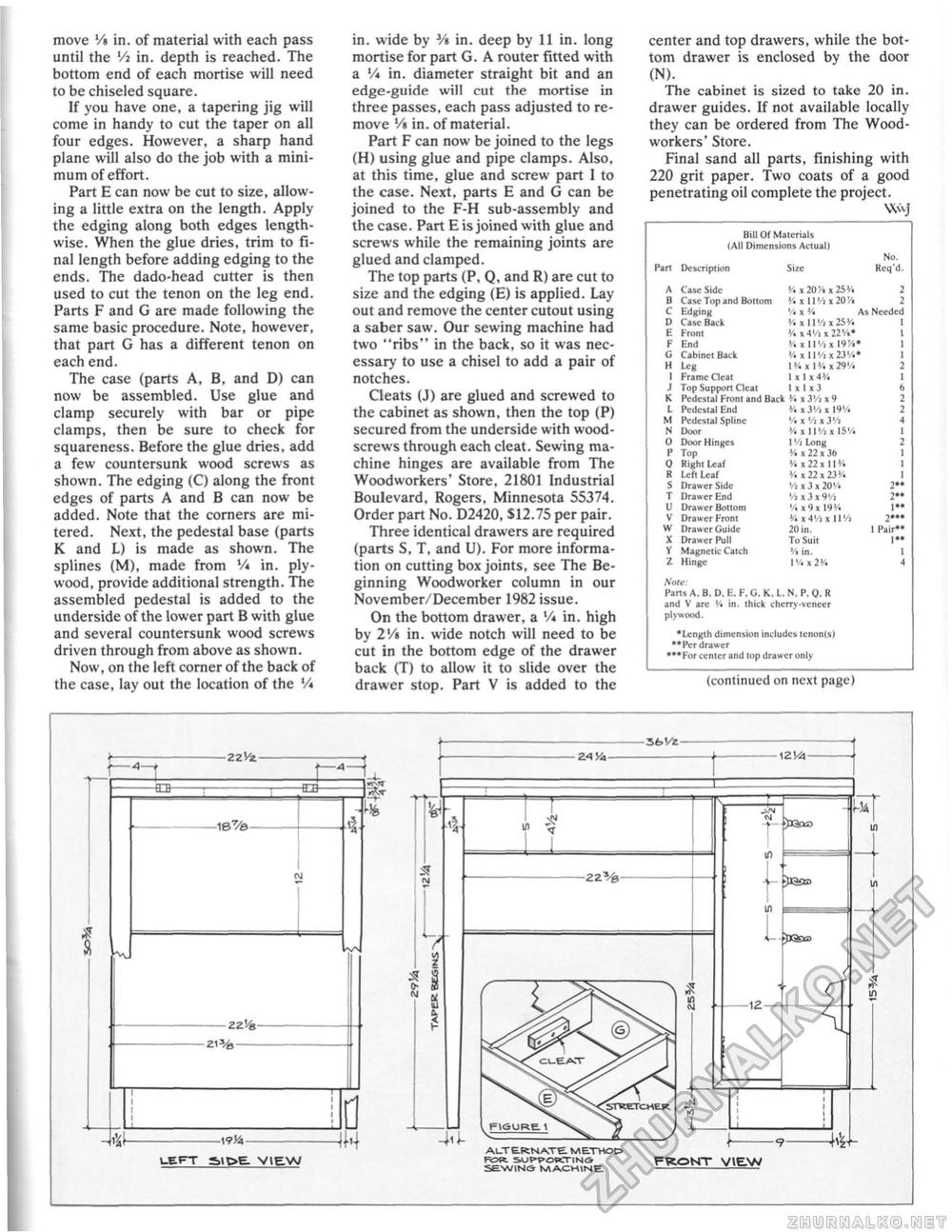
move V% in. of material with each pass until the Vt in. depth is reached. The bottom end of each mortise will need to be chiseled square. If you have one, a tapering jig will come in handy to cut the taper on all four edges. However, a sharp hand plane will also do the job with a minimum of effort. Part E can now be cut to size, allowing a little extra on the length. Apply the edging along both edges lengthwise. When the glue dries, trim to final length before adding edging to the ends. The dado-head cutter is then used to cut the tenon on the leg end. Parts F and G are made following the same basic procedure. Note, however, that part G has a different tenon on each end. The case (parts A, B, and D) can now be assembled. Use glue and clamp securely with bar or pipe clamps, then be sure to check for squareness. Before the glue dries, add a few countersunk wood screws as shown. The edging (C) along the front edges of parts A and B can now be added. Note that the corners are mi-tered. Next, the pedestal base (parts K and L) is made as shown. The splines (M), made from V* in. plywood, provide additional strength. The assembled pedestal is added to the underside of the lower part B with glue and several countersunk wood screws driven through from above as shown. Now, on the left corner of the back of the case, lay out the location of the Vi in. wide by Vi in. deep by 11 in. long mortise for part G. A router fitted with a Vi in. diameter straight bit and an edge-guide will cut the mortise in three passes, each pass adjusted to remove V* in. of material. Part F can now be joined to the legs (H) using glue and pipe clamps. Also, at this time, glue and screw part 1 to the case. Next, parts E and G can be joined to the F-H sub-assembly and the case. Part E is joined with glue and screws while the remaining joints are glued and clamped. The top parts (P, Q, and R) are cut to size and the edging (E) is applied. Lay out and remove the center cutout using a saber saw. Our sewing machine had two "ribs" in the back, so it was necessary to use a chisel to add a pair of notches. Cleats (J) are glued and screwed to the cabinet as shown, then the top (P) secured from the underside with wood-screws through each cleat. Sewing machine hinges are available from The Woodworkers' Store, 21801 Industrial Boulevard, Rogers, Minnesota 55374. Order part No. D2420, $12.75 per pair. Three identical drawers are required (parts S, T, and U). For more information on cutting box joints, see The Beginning Woodworker column in our November/December 1982 issue. On the bottom drawer, a Vi in. high by 2'/« in. wide notch will need to be cut in the bottom edge of the drawer back (T) to allow it to slide over the drawer stop. Part V is added to the center and top drawers, while the bottom drawer is enclosed by the door (N). The cabinet is sized to take 20 in. drawer guides. If not available locally they can be ordered from The Woodworkers' Store. Final sand all parts, finishing with 220 grit paper. Two coats of a good penetrating oil complete the project. ________WvJ Bill Of Materials (All Dimensions Actual) No. Bill Of Materials (All Dimensions Actual) No.
Nate: Parts A. B. D. K. F, G. K, L, N. P. Q, R and V arc % in. thick chcrry-vcnecr plywood. Nate: Parts A. B. D. K. F, G. K, L, N. P. Q, R and V arc % in. thick chcrry-vcnecr plywood. • Length dimension includes tcnon(s) ••Per drawer •••For center and lop drawer only (continued on next page) j—«-f I # a -O- -fLB- -18%>— -ZZV&- -WYa- I N LEFT S>IC>E. VIE.W JH y * % 1 5 S E f 1 ■2AVA- \ZVA- L-L 4*1- FII5URE. < ALTERNATE METHO& Rovt SUF-pdwrrtNG SEW1NS MACHINE -12- -It JGscj £ in v4 FRONT VIEW |
||||||||||||||||||||||||||||||||||||||||||||||||||||||||||||||||||||||||||||||||||||||||||||||||||||||||||||


