Woodworker's Journal 1984-8-4, страница 45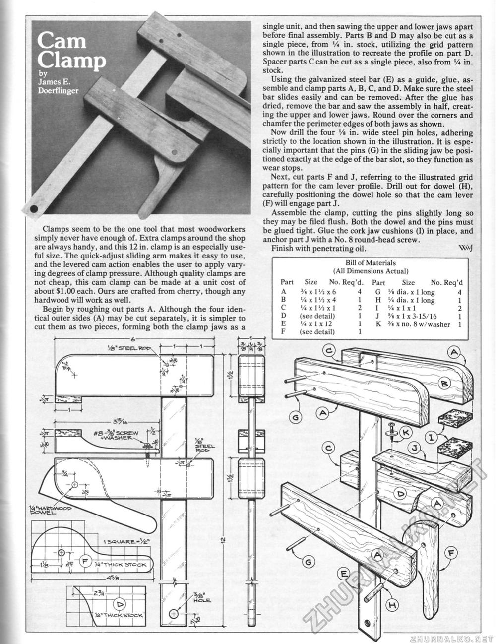
Bill of Materials (All Dimensions Actual) Size No. Req'd '/« dia. x 1 long 4 V* dia. x 1 long 1 '/* x 1 x 1 2 '/ix 1 x 3-15/16 1 y« x no. 8 w/washer 1 Bill of Materials (All Dimensions Actual)
Clamps seem to be the one tool that most woodworkers simply never have enough of. Extra clamps around the shop are always handy, and this 12 in. clamp is an especially useful size. The quick-adjust sliding arm makes it easy to use, and the levered cam action enables the user to apply varying degrees of clamp pressure. Although quality clamps are not cheap, this cam clamp can be made at a unit cost of about $1.00each. Ours are crafted from cherry, though any hardwood will work as well. Begin by roughing out parts A. Although the four identical outer sides (A) may be cut separately, it is simpler to cut them as two pieces, forming both the clamp jaws as a single unit, and then sawing the upper and lower jaws apart before final assembly. Parts B and D may also be cut as a single piece, from V* in. stock, utilizing the grid pattern shown in the illustration to recreate the profile on part D. Spacer parts C can be cut as a single piece, also from V* in. stock. Using the galvanized steel bar (E) as a guide, glue, assemble and clamp parts A, B, C, and D. Make sure the steel bar slides easily and can be removed. After the glue has dried, remove the bar and saw the assembly in half, creating the upper and lower jaws. Round over the corners and chamfer the perimeter edges of both jaws as shown. Now drill the four '/» in. wide steel pin holes, adhering strictly to the location shown in the illustration. It is especially important that the pins (G) in the sliding jaw be positioned exactly at the edge of the bar slot, so they function as wear stops. Next, cut parts F and J, referring to the illustrated grid pattern for the cam lever profile. Drill out for dowel (H), carefully positioning the dowel hole so that the cam lever (F) will engage part J. Assemble the clamp, cutting the pins slightly long so they may be filed flush. Both the dowel and the pins must be glued tight. Glue the cork jaw cushions (I) in place, and anchor part J with a No. 8 round-head screw. Finish with penetrating oil. WVJ |
||||||||||||||||||||||||||||


