Woodworker's Journal 1984-8-5, страница 40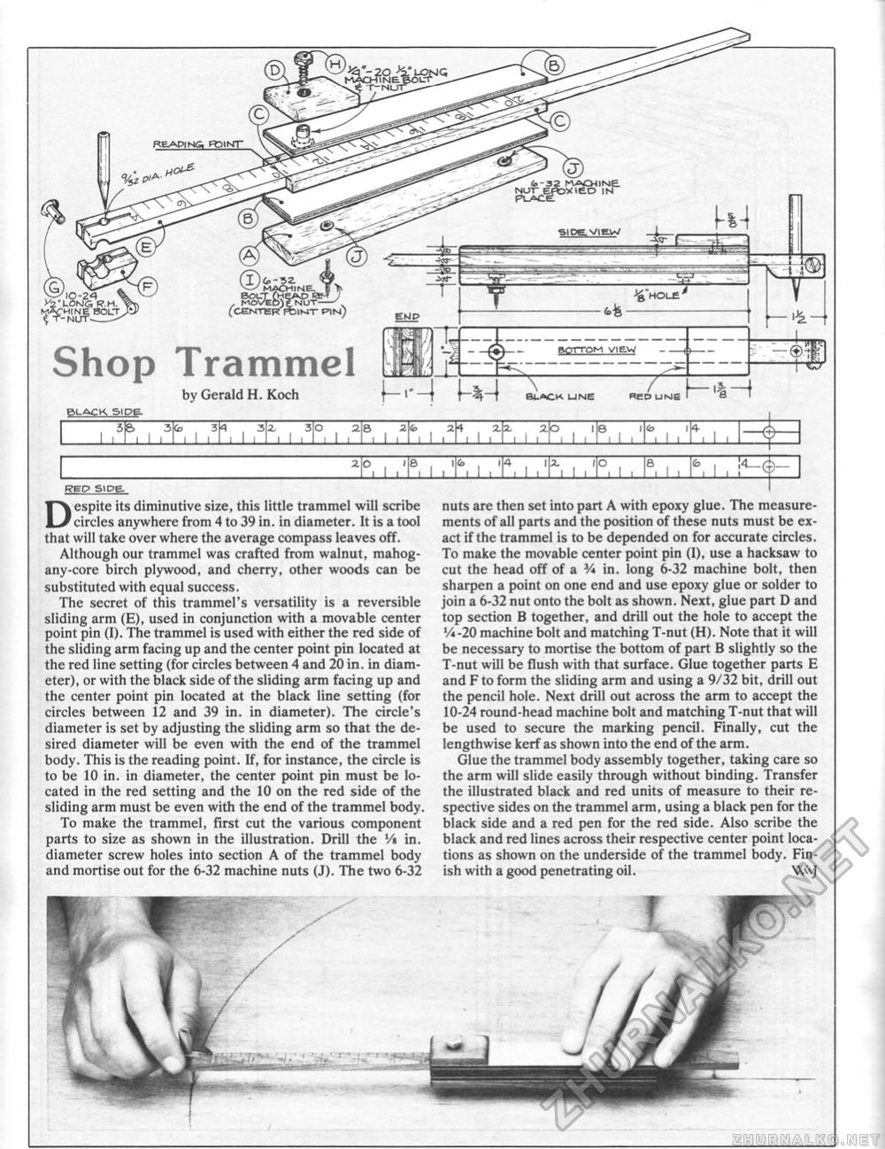
REP Slpe REP Slpe Despite its diminutive size, this little trammel will scribe circles anywhere from 4 to 39 in. in diameter. It is a tool that will take over where the average compass leaves off. Although our trammel was crafted from walnut, mahogany-core birch plywood, and cherry, other woods can be substituted with equal success. The secret of this trammel's versatility is a reversible sliding arm (E), used in conjunction with a movable center point pin (I). The trammel is used with either the red side of the sliding arm facing up and the center point pin located at the red line setting (for circles between 4 and 20 in. in diameter), or with the black side of the sliding arm facing up and the center point pin located at the black line setting (for circles between 12 and 39 in. in diameter). The circle's diameter is set by adjusting the sliding arm so that the desired diameter will be even with the end of the trammel body. This is the reading point. If, for instance, the circle is to be 10 in. in diameter, the center point pin must be located in the red setting and the 10 on the red side of the sliding arm must be even with the end of the trammel body. To make the trammel, first cut the various component parts to size as shown in the illustration. Drill the Vt in. diameter screw holes into section A of the trammel body and mortise out for the 6-32 machine nuts (J). The two 6-32 ^■f-NUfZZ^' -------------- Shop Trammel by Gerald H. Koch BifreK.sipg. nuts are then set into part A with epoxy glue. The measurements of all parts and the position of these nuts must be exact if the trammel is to be depended on for accurate circles. To make the movable center point pin (1), use a hacksaw to cut the head off of a V* in. long 6-32 machine bolt, then sharpen a point on one end and use epoxy glue or solder to join a 6-32 nut onto the bolt as shown. Next, glue part D and top section B together, and drill out the hole to accept the Vi-20 machine bolt and matching T-nut (H). Note that it will be necessary to mortise the bottom of part B slightly so the T-nut will be flush with that surface. Glue together parts E and F to form the sliding arm and using a 9/32 bit, drill out the pencil hole. Next drill out across the arm to accept the 10-24 round-head machine bolt and matching T-nut that will be used to secure the marking pencil. Finally, cut the lengthwise kerf as shown into the end of the arm. Glue the trammel body assembly together, taking care so the arm will slide easily through without binding. Transfer the illustrated black and red units of measure to their respective sides on the trammel arm, using a black pen for the black side and a red pen for the red side. Also scribe the black and red lines across their respective center point locations as shown on the underside of the trammel body. Finish with a good penetrating oil. Wvj ekjp |
|||||||||||||||||||||||||||||||||||||||||||||


