Woodworker's Journal 1985-9-1, страница 63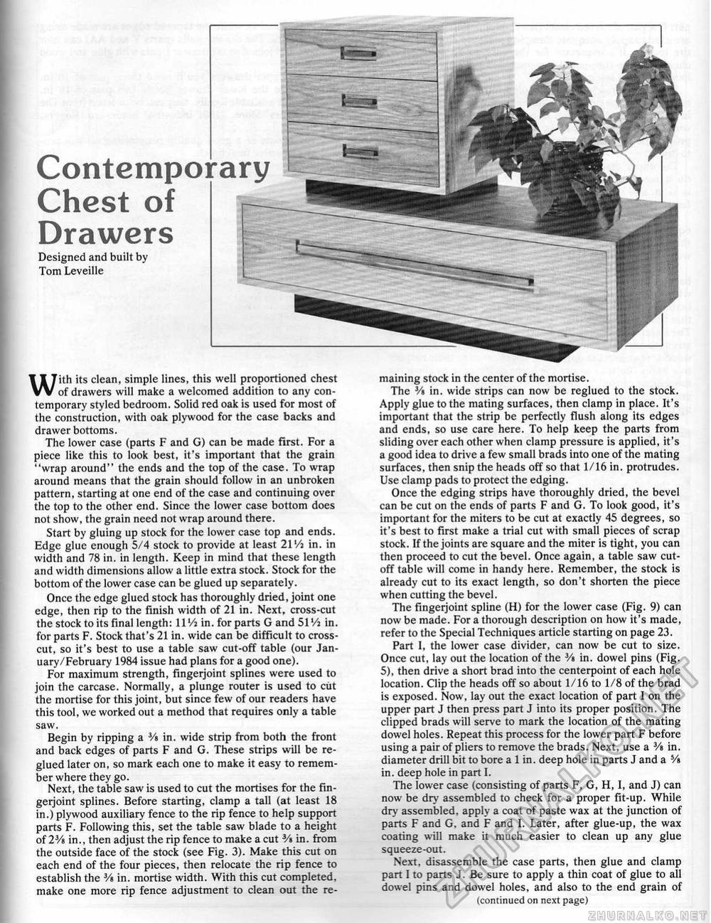
Contemporary Chest of Drawers Designed and built by Tom Leveille With its clean, simple lines, this well proportioned chest of drawers will make a welcomed addition to any contemporary styled bedroom. Solid red oak is used for most of the construction, with oak plywood for the case backs and drawer bottoms. The lower case (parts F and G) can be made first. For a piece like this to look best, it's important that the grain "wrap around" the ends and the top of the case. To wrap around means that the grain should follow in an unbroken pattern, starting at one end of the case and continuing over the top to the other end. Since the lower case bottom does not show, the grain need not wrap around there. Start by gluing up stock for the lower case top and ends. Edge glue enough 5/4 stock to provide at least 21 Vi in. in width and 78 in. in length. Keep in mind that these length and width dimensions allow a little extra stock. Stock for the bottom of the lower case can be glued up separately. Once the edge glued stock has thoroughly dried, joint one edge, then rip to the finish width of 21 in. Next, cross-cut the stock to its final length: 11 Vi in. for parts G and 51 Vi in. for parts F. Stock that's 21 in. wide can be difficult to crosscut, so it's best to use a table saw cut-off table (our January/February 1984 issue had plans for a good one). For maximum strength, fingerjoint splines were used to join the carcase. Normally, a plunge router is used to cut the mortise for this joint, but since few of our readers have this tool, we worked out a method that requires only a table saw. Begin by ripping a 3/s in. wide strip from both the front and back edges of parts F and G. These strips will be re-glued later on, so mark each one to make it easy to remember where they go. Next, the table saw is used to cut the mortises for the fingerjoint splines. Before starting, clamp a tall (at least 18 in.) plywood auxiliary fence to the rip fence to help support parts F. Following this, set the table saw blade to a height of 2¥s in., then adjust the rip fence to make a cut 3A in. from the outside face of the stock (see Fig. 3). Make this cut on each end of the four pieces, then relocate the rip fence to establish the Vt, in. mortise width. With this cut completed, make one more rip fence adjustment to clean out the re maining stock in the center of the mortise, The 3/s in. wide strips can now be reglued to the stock. Apply glue to the mating surfaces, then clamp in place. It's important that the strip be perfectly flush along its edges and ends, so use care here. To help keep the parts from sliding over each other when clamp pressure is applied, it's a good idea to drive a few small brads into one of the mating surfaces, then snip the heads off so that 1/16 in. protrudes. Use clamp pads to protect the edging. Once the edging strips have thoroughly dried, the bevel can be cut on the ends of parts F and G. To look good, it's important for the miters to be cut at exactly 45 degrees, so it's best to first make a trial cut with small pieces of scrap stock. If the joints are square and the miter is tight, you can then proceed to cut the bevel. Once again, a table saw cutoff table will come in handy here. Remember, the stock is already cut to its exact length, so don't shorten the piece when cutting the bevel. The fingerjoint spline (H) for the lower case (Fig. 9) can now be made. For a thorough description on how it's made, refer to the Special Techniques article starting on page 23. Part 1, the lower case divider, can now be cut to size. Once cut, lay out the location of the 3/> in. dowel pins (Fig. 5), then drive a short brad into the centerpoint of each hole location. Clip the heads off so about 1/16 to 1/8 of the brad is exposed. Now, lay out the exact location of part I on the upper part J then press part J into its proper position. The clipped brads will serve to mark the location of the mating dowel holes. Repeat this process for the lower part F before using a pair of pliers to remove the brads. Next, use a 3/a in. diameter drill bit to bore a 1 in. deep hole in parts J and a 5/s in. deep hole in part I. The lower case (consisting of parts F, G, H, I, and J) can now be dry assembled to check for a proper fit-up. While dry assembled, apply a coat of paste wax at the junction of parts F and G, and F and I. Later, after glue-up, the wax coating will make it much easier to clean up any glue squeeze-out. Next, disassemble the case parts, then glue and clamp part I to parts J, Be sure to apply a thin coat of glue to all dowel pins and dowel holes, and also to the end grain of (continued on next page) |


