Woodworker's Journal 1985-9-1, страница 64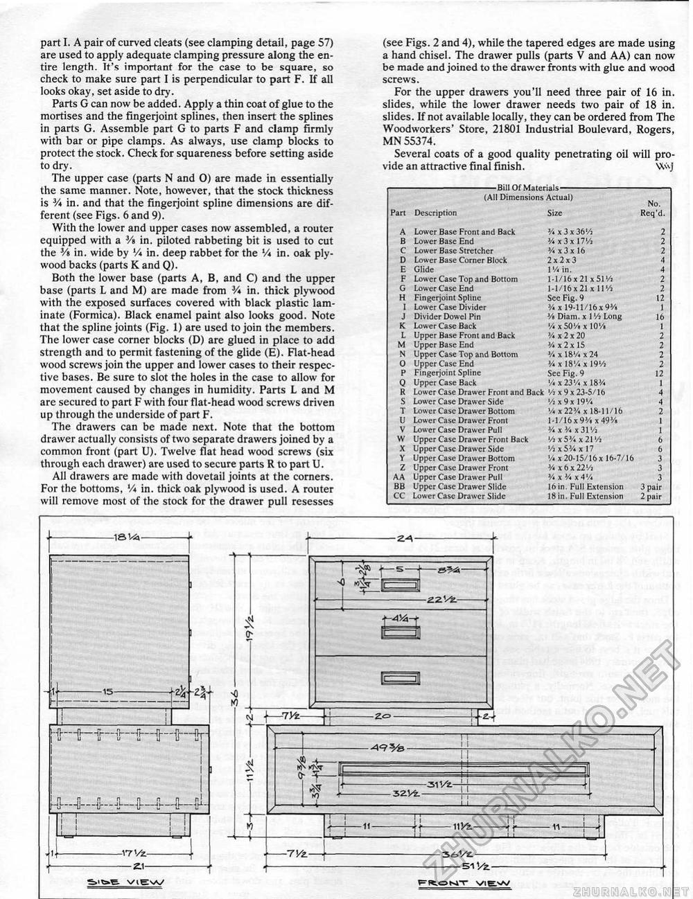
part I. A pair of curved cleats (see clamping detail, page 57) are used to apply adequate clamping pressure along the entire length. It's important for the case to be square, so check to make sure part I is perpendicular to part F. If all looks okay, set aside to dry. Parts G can now be added. Apply a thin coat of glue to the mortises and the fingerjoint splines, then insert the splines in parts G. Assemble part G to parts F and clamp firmly with bar or pipe clamps. As always, use clamp blocks to protect the stock. Check for squareness before setting aside to dry. The upper case (parts N and 0) are made in essentially the same manner. Note, however, that the stock thickness is Vt in. and that the fingerjoint spline dimensions are different (see Figs. 6 and 9). With the lower and upper cases now assembled, a router equipped with a V% in. piloted rabbeting bit is used to cut the 3/s in. wide by V* in. deep rabbet for the Vt in. oak plywood backs (parts K and Q). Both the lower base (parts A, B, and C) and the upper base (parts L and M) are made from Vt in. thick plywood with the exposed surfaces covered with black plastic laminate (Formica). Black enamel paint also looks good. Note that the spline joints (Fig. 1) are used to join the members. The lower case corner blocks (D) are glued in place to add strength and to permit fastening of the glide (E). Flat-head wood screws join the upper and lower cases to their respective bases. Be sure to slot the holes in the case to allow for movement caused by changes in humidity. Parts L and M are secured to part F with four flat-head wood screws driven up through the underside of part F. The drawers can be made next. Note that the bottom drawer actually consists of two separate drawers joined by a common front (part U). Twelve flat head wood screws (six through each drawer) are used to secure parts R to part U. All drawers are made with dovetail joints at the corners. For the bottoms, Vt in. thick oak plywood is used. A router will remove most of the stock for the drawer pull resesses (see Figs. 2 and 4), while the tapered edges are made using a hand chisel. The drawer pulls (parts V and A A) can now be made and joined to the drawer fronts with glue and wood screws. For the upper drawers you'll need three pair of 16 in. slides, while the lower drawer needs two pair of 18 in. slides. If not available locally, they can be ordered from The Woodworkers' Store, 21801 Industrial Boulevard, Rogers, MN 55374, Several coats of a good quality penetrating oil will provide an attractive final finish. W\j -Bill Of Materials- (All Dimensions Actual) No. -Bill Of Materials- (All Dimensions Actual) No.
|


