Woodworker's Journal 1985-9-3, страница 34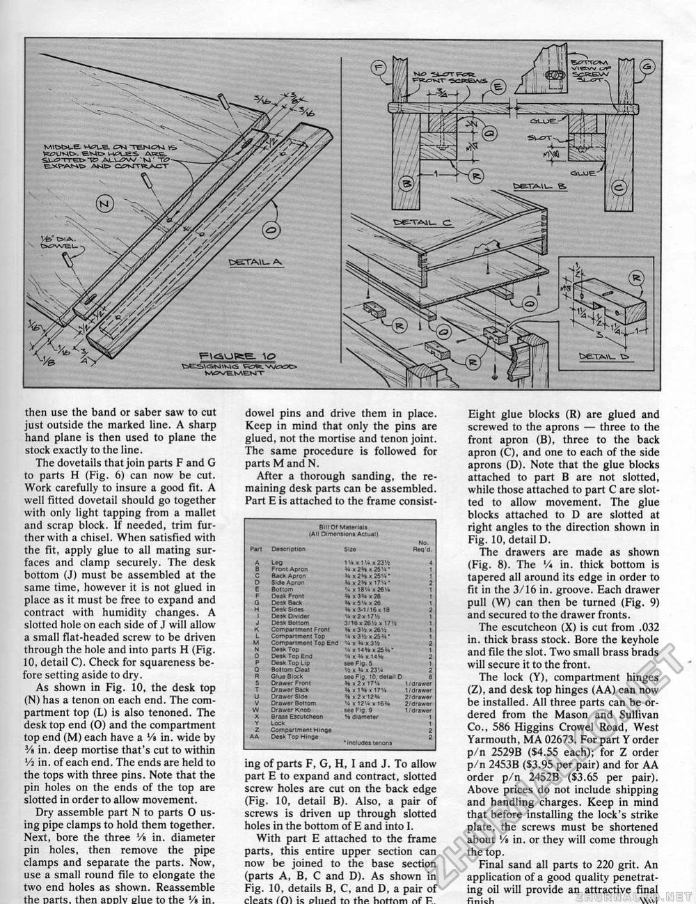
then use the band or saber saw to cut just outside the marked line. A sharp hand plane is then used to plane the stock exactly to the line. The dovetails that join parts F and G to parts H (Fig. 6) can now be cut. Work carefully to insure a good fit. A weil fitted dovetail should go together with only light tapping from a mallet and scrap block. If needed, trim further with a chisel. When satisfied with the fit, apply glue to all mating surfaces and clamp securely. The desk bottom (J) must be assembled at the same time, however it is not glued in place as it must be free to expand and contract with humidity changes. A slotted hole on each side of J will allow a small flat-headed screw to be driven through the hole and into parts H (Fig. 10, detail C). Check for squareness before setting aside to dry. As shown in Fig. 10, the desk top (N) has a tenon on each end. The compartment top (L) is also tenoned. The desk top end (0) and the compartment top end (M) each have a Vi in. wide by Vt in, deep mortise that's cut to within Vi in. of each end. The ends are held to the tops with three pins. Note that the pin holes on the ends of the top are slotted in order to allow movement. Dry assemble part N to parts 0 using pipe clamps to hold them together. Next, bore the three Vt in. diameter pin holes, then remove the pipe damps and separate the parts. Now, use a small round file to elongate the two end holes as shown. Reassemble the Darts, then anolv slue to the Vs in. dowel pins and drive them in place. Keep in mind that only the pins are glued, not the mortise and tenon joint. The same procedure is followed for parts M and N. After a thorough sanding, the remaining desk parts can be assembled. Part E is attached to the frame consist- Bill 01 Malarial! I All Dimenslona Aelunl) No, Bill 01 Malarial! I All Dimenslona Aelunl) No,
' includes tenons ' includes tenons ing of parts F, G, H, I and J. To allow part E to expand and contract, slotted screw holes are cut on the back edge (Fig. 10, detail B). Also, a pair of screws is driven up through slotted holes in the bottom of E and into I. With part E attached to the frame parts, this entire upper section can now be joined to the base section (parts A, B, C and D). As shown in Fig. 10, details B, C, and D, a pair of cleats fO) is plueri to the hottnm nf R Eight glue blocks (R) are glued and screwed to the aprons — three to the front apron (B), three to the back apron (C), and one to each of the side aprons (D). Note that the glue blocks attached to part B are not slotted, while those attached to part C are slotted to allow movement. The glue blocks attached to D are slotted at right angles to the direction shown in Fig. 10, detail D. The drawers are made as shown (Fig. 8). The V* in. thick bottom is tapered all around its edge in order to fit in the 3/16 in. groove, Each drawer pull (W) can then be turned (Fig. 9) and secured to the drawer fronts. The escutcheon (X) is cut from .032 in. thick brass stock. Bore the keyhole and file the slot. Two small brass brads will secure it to the front. The lock (Y), compartment hinges (Z), and desk top hinges (AA) can now be installed. All three parts can be ordered from the Mason and Sullivan Co., 586 Higgins Crowel Road, West Yarmouth, MA 02673. For part Y order p/n 2529B ($4.55 each); for Z order p/n 2453B (S3.95 per pair) and for AA order p/n 2452B ($3.65 per pair). Above prices do not include shipping and handling charges. Keep in mind that before installing the lock's strike plate, the screws must be shortened about Vt in. or they will come through the top. Final sand all parts to 220 grit. An application of a good quality penetrating oil will provide an attractive final finish Wvi |


