Woodworker's Journal 1985-9-6, страница 53
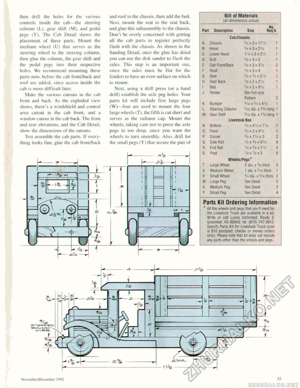
then drill the holes for the various controls inside the cab—the steering column (Lh gear shift (M), and pedal pegs (Y). The Cab Detail shows the placement of these parts. Mount the medium wheel (U) that serves as the steering wheel to the steering column, then glue the column, the gear shift and the pedal pegs into their respective holes. We recommend mounting these parts now, before the cab front/back and roof are added, since access inside ihe cab is more difficult later. Make the various cutouts in the cab from and back. As the exploded view shows, there's a windshield and control area cutout in the cab front, and a window cutout in the cab back. The front and rear elevations, and the Cab Detail, show ihe dimensions of the cutouts. Test assemble the cab parts. If everything looks fine, glue the cab front/back and roof to the chassis, then add the bed. Next, mount the seat to the seat back, and glue this subassembly to the chassis. Don't be overly concerned with getting all the cab parts to register perfectly flush with the chassis. As shown in the Sanding Detail, once the glue has dried you can use the disk sander to flush the sides. This step is an important one. since the sides must be flat for the fenders to have an even surface on w hich to mount. Next, using a drill press (or a hand drill) establish the axle peg holes. Your parts kit will include five large pegs (W)—four are used to mount the four large wheels (T), the fifth is cut short and serves as the radiator cap. Mount the wheels, taking care no! to press the axle pegs in too deep, since you want the wheels to turn smoothly. Also, drill for the small pegs (Y) that secure the pair of
■HAs Niivember/DccL-mbcr 1992 |
||||||||||||||||||||||||||||||||||||||||||||||||||||||||||||||||||||||||||||||||||||||||||||||||||||||


