Woodworker's Journal 1985-9-6, страница 51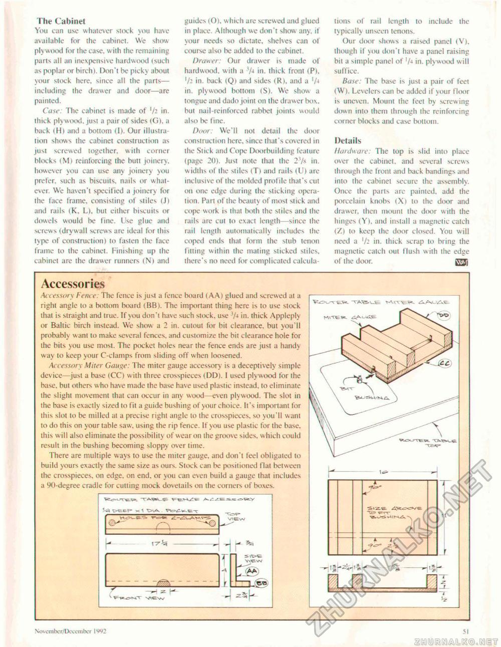
The Cabinet You can use whatever stock you have available for the cabinet. We show plywood for the case, with the remaining parts all an inexpensive hardwood (such as poplar or birch). Don't be picky about your stock here, since all the parts— including the drawer and door—are painted. Case: Tlie cabinet is made of V2 in. thick plywood, just a pair of sides <G), a back (H> and a bottom (I). Our illustra lion shows the cabinet construction as just screwed together, with corner blocks 1 Mi reinforcing the butt joinery, however you can use any joinery you prefer, such as biscuits, nails or whatever. We haven't specified a joinery for ihe face frame, consisting of stiles (J) and rails (K. L>, but either biscuits or dowels would be fine. Use glue and screws (drywall screws are ideal for this type of construction) to fasten the face frame to the cabinet. Finishing up the cabinet are the drawer runners (N) ami guides (0), which are screwed and glued in place. Although we don't show any, if your needs so dictate, shelves can of course also be added to the cabinet. Drawer: Our drawer is made of hardwood, w ith a V*« in. thick front (P). ]/i in. back (Q) and sides (R). and a 'A in. plywood bottom (S). We show a tongue and dado joint on the drawer box. but nail-reinforced rabbet joinis would also be fine. Door: We'll not detail the door construction here, since that's covered in the Stick and Cope Doorbuilding feature (page 20}. Just note that the 2'/s in. w idths of the sliles (Tl and rails (U) are inclusive of the molded profile that's cut on one edge during the sticking operation. Pari of the beauty of most stick and cope work is thai both the stiles and the rails are cut to exact length—since the rail length automatically includes the coped ends that form the stub tenon fitting within the mating sticked stiles, there's no need for complicated calcula tions of rail length lo include the typically unseen tenons. Our door shows a raised panel (V). though if you don't have a panel raising bit a simple panel of 1 in. plywood will suffice. Base: The base is just a pair of feet (W). Levelers can be added if your floor is uneven. Mount the feet by screwing down into I hem I h rough the reinforcing corner blocks and case bottom. Details Hardware: The top is slid into place over the cabinet, and several screws through the front and hack bandings and into ihe cabinet secure the assembly. Once the parts are painted, add the porcelain knobs (Xl to the door and drawer, then mount the door with the hinges (Y). and install a magnetic catch (7.) to keep ihe door closed. You will need a in. thick scrap 10 bring the magnetic catch out flush wiih the edge of the door. gTJj Accessories .4<cessory Fence: The fence is just a fence board (AA) glued and screwed at a right angle to a bottom board (BB). The important thing here is to use stock that is straight and true. If you don 't have such stock, use SM in. thick Appleply or Baltic birch instead. We show a 2 in. cutout for bit clearance, but you'll probably want to make several fences, and customize the bit clearance hole for the bits you use most. The pocket holes near the fence ends are jusi a hand} way lo keep your C-clamps from sliding off when loosened. Accessory Miter Gauge: The miter gauge accessory is a deceptively simple device—just a base (CC) w ith three crosspieces (DD). I used plywood for the base, hut others w ho have made the base have used plastic instead, to eliminate the slight movement that can occur in any wood—even plywood. The slot in the base is exactly sized to fit a guide bushing of your choice. It's important for this slot lo be milled ai a precise right angle to the crosspieces. so you'll w ant to do this on your table saw . using the rip fence. If you use plastic for the base, this will also eliminate ihe possibility of wear on the groove sides, which could result in the bushing becoming sloppy over time. There are multiple ways to use the miter gauge, and don't feel obligated to build yours exactly the same size as ours. Slock can be positioned flat between ihe crosspieces. on edge, on end. or you can even build a gauge that includes a 90-degree cradle for cutting mock dovetails on the corners of boxes. h (7% ---^__ - K- »t ~~;*—a— Nov ember/December 1992 51 |


