Woodworker's Journal 1994-18-3, страница 51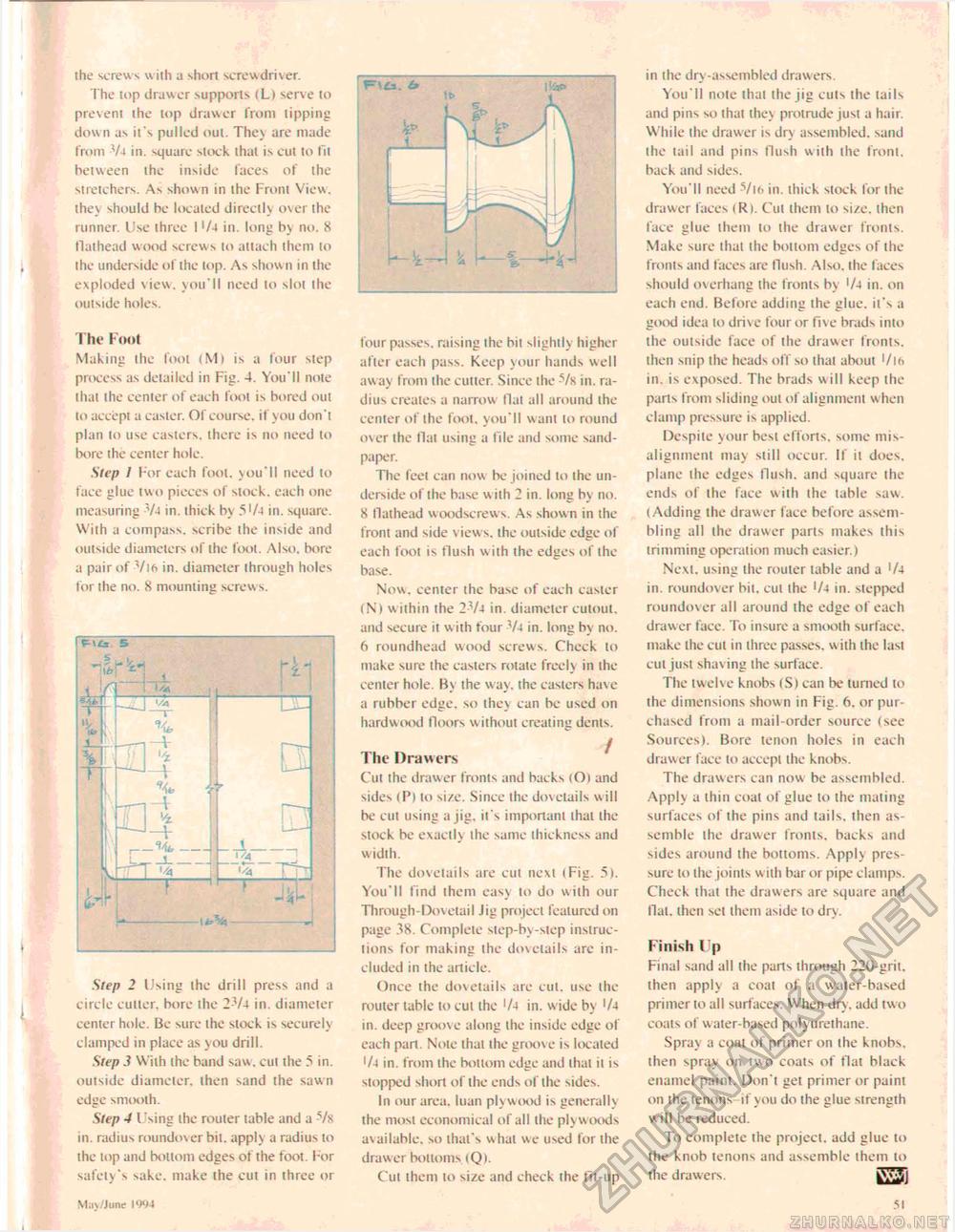
the screws with a short screwdriver. The top drawer supports (Li serve to prevent the lop drawer from tipping down as it's pulled out. Thev are made from 74 in. square slock thai is cut to fit between the inside faces of the stretchers. As shown in the Front View, they should he located directly over the runner. Use three I '/4 in. long by no. 8 flathead wood screws to attach them to the underside of the lop. As show 11 in the exploded view, you'll need to slot the outside holes. The Foot Making the foot (M) is a lour step process as detailed in Fig. 4. You'll note thai the center of each foot is bored out to accept a caster. Of course, if you don't plan to use casters, there is no need to bore the center hole. Step I For each foot, you'll need lo face glue two pieces of stock, each one measuring -V4 in. thick bv 5'/4 in. square. With a compass, scribe the inside and outside diameters of the fool. Also, bore a pair of Vi6 in. diameter through holes for the no. 8 mounting screws. Step 2 Using ihe drill press and a circle culler, bore the 2-V4 in. diameter center hole. Be sure ihe stock is securely clamped in place as you drill. Step.? Wiih the band saw. cut the 5 in. outside diameter, then sand the sawn edge smooth. Step 4 Using the router table and a -Vx in. radius roundover bit. apply a radius to the lop and bottom edges of the foot. For safety's sake, make the cut in three or £ four passes, raising the bit slightly higher after each pass. Keep your hands well away from the cutter. Since the -s/x in. radius creates a narrow Hat all around the center of the foot, you'll want lo round over the Hat using a File and some sandpaper. The feet can now be joined to the underside of the base w ith 2 in. long by no. 8 flathead woodscrews. As shown in the front and side view s, ihe outside edge of each foot is flush w ith the edges of the base. Now. center the base of each easier (N) within the 2-Vj in. diameter cutout, and secure it w ith four V4 in. long by no. 6 roundhead wood screws. Check to make sure the casters rotate freely in the center hole. By the w ay. the casters have a rubber edge, so they can be used on hardwood floors without creating dents. The Drawers Cut the drawer fronts and backs (O) and sides (P) to size. Since the dovetails will be cut using a jig. it's important that ihe stock be exactly the same thickness and width. The dovetails are cut next (Fig. 5). You'll find them easy to do wiih our Through-Dovetail Jig project featured on page 38. Complete step-by-step instructions for making the dovclails are included in the article. Once the dovetails are cut. use the router tabic to cut the '/4 in. w ide by '/4 in. deep groove along the inside edge of each pari. Nole that ihe groove is located '/4 in. from the bottom edge and lhal it is stopped short of ihe ends of the sides. In our area, luan plywood is generally the most economical of all ihe plywoods available, so that's whal we used for the drawer bottoms (Q). Cut them to size and check the fit-up in the dry-assembled drawers. You'll note that the jig euls the tails and pins so that they protrude just a hair. While the drawer is dry assembled, sand the tail and pins flush with the front, back and sides. You'll need Vt6 in. thick stock for the drawer faces <R). Cut them to size, then face glue them to the drawer fronts. Make sure lhal the bottom edges of the fronts and faces are flush. Also, the faces should overhang the fronts by '/4 in. on each end. Before adding the glue, it's a good idea to drive four or five brads into the outside face of the drawer fronts, then snip the heads off so that about '/l6 in. is exposed. The brads w ill keep the parts from sliding out of alignment when clamp pressure is applied. Despite your best efforts, some misalignment may still occur. If it does, plane the edges flush, and square the ends of the face with the table saw. (Adding the drawer face before assembling all the drawer parts makes this trimming operation much easier.) Next, using the router table and a '/4 in. roundover bit, cut the '/4 in. stepped roundover all around the edge of each drawer face. To insure a smooth surface, make the cut in three passes, with the last cut just shav ing the surface. The twelve knobs (S) can be turned lo the dimensions shown in Fig. 6. or purchased from a mail-order source (see Sources). Bore tenon holes in each draw er face lo accept the knobs. The drawers can now be assembled. Apply a thin coal of glue to the mating surfaces of ihe pins and tails, then assemble the drawer fronts, backs and sides around the bottoms. Apply pressure to Ihe joints w ith bar or pipe clamps. Check that the drawers are square and flai. ihen sei them aside to dry. Finish Up Final sand all the pans through 220-grit. then apply a coat of a water-based primer to all surfaces. When dry. add two coats of water-based polyureihane. Sprav a coat of primer on the knobs, then spray on two coats of flat black enamel paint. Don't get primer or paint on the tenons if you do the glue sirength will be reduced. To complete the project, add glue to the knob tenons and assemble them to the drawers. IftBIl May/June 1994 51 |


