Woodworker's Journal 1994-18-3, страница 50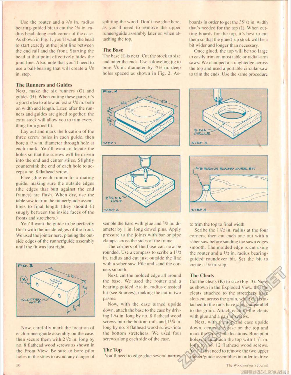
Use the router and a -Vx in. radius hearing-guided bit to cut the -s/x in. radius bead along each corner of the case. As shown in Fig. 1. you'll want the bead to start exactly at the joint line between the end rail and the front. Starling the bead at that point effectively hides the joint line. Also, note that you'll need to use a ball-bearing that will create a •/« in. step. The Kunners and Guides Next, make the six runners (G) and guides (H). When cutting these parts, it's a good idea to allow an extra '/x in. both on width and length. Later, after the runners and guides are glued together, the extra stock w ill allow you to trim even -thing for a good fit. Lay out and mark the location of the three screw holes in each guide, then bore a Vift in. diameter through hole at each mark. You'll want to locate the holes so that the screws will be driven into the end and center stiles. Slightly countersink the end of each hole to accept a no. 8 flathead screw. Face glue each runner to a mating guide, making sure the outside edges (the edges that butt against the end frames) are flush. When dry, use the table saw to trim the runner/guide assemblies to final length (they should fit snugly between the inside faces of the fronts and stretchers.) You'll want the guide to be perfectly flush with the inside edges of the front. We used the jointer here, planing the outside edges of the runner/guide assembly until the fit was just right. Now. carefully mark the location of each runner/guide assembly on the case, then secure them with 2'/2 in. long by no. 8 flathead wood screws as show n in the Front View. Be sure to bore pilot holes in the stiles to a\oid any danger of splitting the wood. Don't use glue here, as you'll need to remove the upper runner/guide assembly later on w hen attaching the top. The Base The base (I) is next. Cut the stock to size and miter the ends. Use a dow eling jig to bore Vx in. diameter by in. deep holes spaced as shown in Fig. 2. As- a semblc the base with glue and Vx in. diameter by 1 in. long dowel pins. Apply pressure to the joints with bar or pipe clamps across the sides of the frame. The corners of the base can now be rounded. Use a compass to scribe a I '/2 in. radius and cut just outside the line with a saber saw. File and sand the corners smooth. Next, cut the molded edge all around the base. We used the router and a bearing-guided -Vl6 in. radius classical bit (see Sources), making the cut in two passes. Now. with the case turned upside down, attach the base to the case by driving I-V4 in. long b\ no. 8 flathead wood screws into the bottom rails and I '/-i in. long by no. 8 flathead wood screws into the bottom stretchers. We used four screws along each side of the case. The Top You'll need to edge glue several narrow boards in order to get the 35'/2 in. w idth that's needed for the top (J). When cutting boards for the lop. it's best to cut them so that the glued-up stock w ill be a bit wider and longer than necessary. Once glued, the lop will be too large to easily trim on most table or radial-arm saw s. We damped a straightedge across the lop and used a portable circular saw to trim the ends. Use the same procedure to trim the top to final w idth. Scribe the 1 '/2 in. radius at the four corners, then cut each one out with a saber saw before sanding the saw n edges smooth. The molded edge is cut using the router and a >/2 in. radius bearing-guided roundovcr bit. Set the bit to create a l/xin. step. The Cleats Cut the cleats (K) to size (Fig. 3). Note, as shown in the Exploded View, that the cleats attached to the stretchers have slots cut across the grain, while cleats attached to the rails have slots cut parallel to the grain. Attach each of the cleats w ith glue and a pair of screw s. Next, with the lop and case upside down, center the case on the top and mark the screw hole locations. Bore pilot holes, then attach the top with I '/4 in. long by no. 12 flaihcad wood screws. You'll first need to remove the two upper runner/guide assemblies in order to drive STELP 3 5 C\V..CXJE. 50 The W«HKlvsorker"s Journal |


