Woodworker's Journal 2001-25-2, страница 52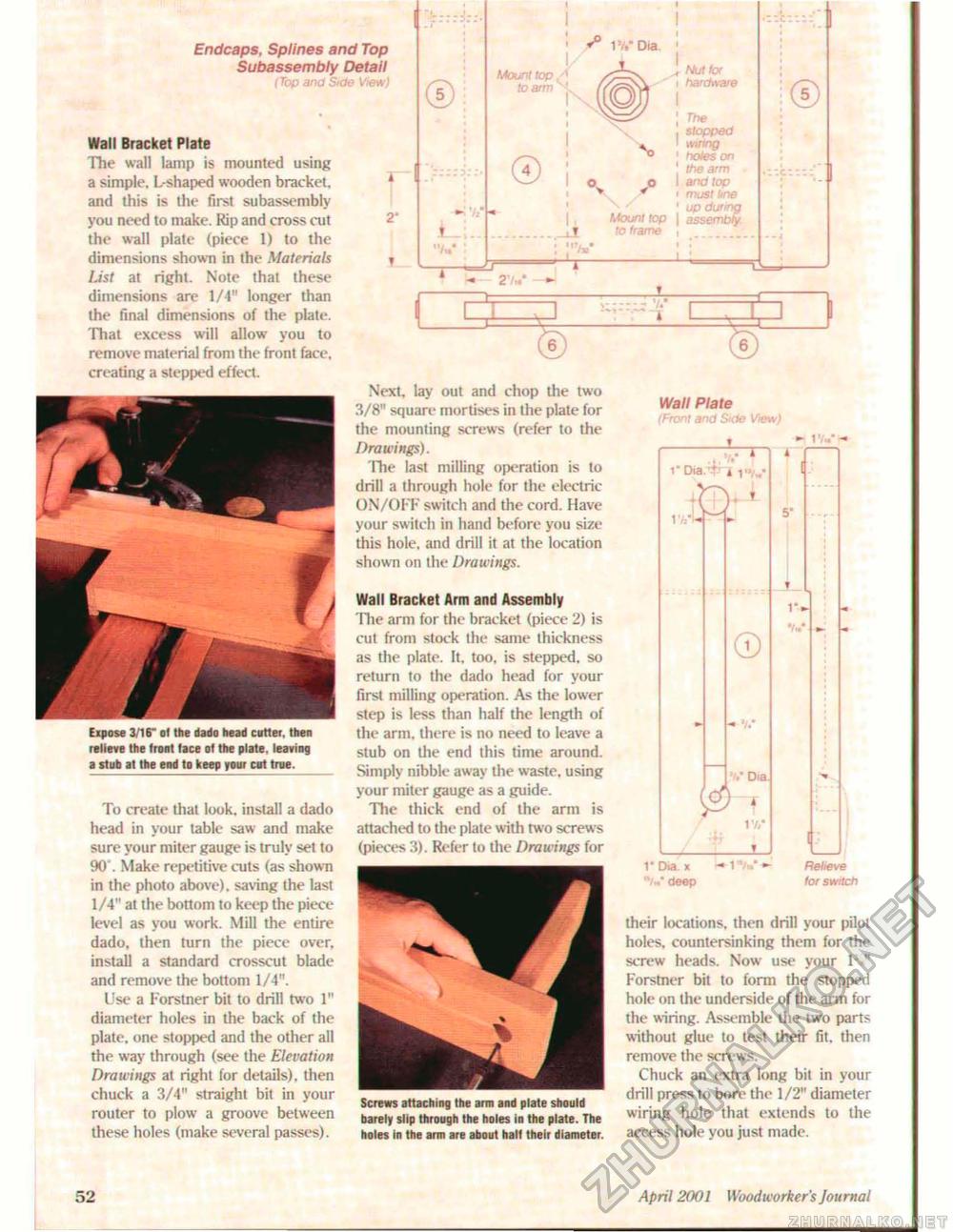
Endcaps, Splines and Top Subassembly Detail (Top and Side View) Wall Bracket Plate The wall lamp is mounted using a simple. L-shaped wooden bracket, and this is the first subassembly you need to make. Rip and cross cut the wall plate (piece 1) to the dimensions shown in the Materials List at right. Note that these dimensions are 1/4" longer than the final dimensions of the plate. That excess will allow you to remove material from the front face, creating a stepped effect. Expose 3/16" of ttie dado head cutter, then relieve the front lace of the plate, leaving a stub at the end to keep your cut true. To create that look, install a dado head in your table saw and make sure your miter gauge is truly set to 90'. Make repetitive cuts (as shown in the photo above), saving the last 1/4" at the bottom to keep the piece level as you work. Mill the entire dado, then turn the piece over, install a standard crosscut blade and remove the bottom 1/4". Use a Forstner bit to drill two 1" diameter holes in the back of the plate, one stopped and the other all the way through (see the Elevation Drawings at right for details), then chuck a 3/4" straight bit in your router to plowr a groove between these holes (make several passes). i 2" © - 'ft i hi 1VDia. Mount top to arm © i it '•V ~T— Mount top to frame J, Nut for i hardware The slopped wiring holes on the arm and lop must line up during assembly © CI © Screws attaching the aim and plate should barely slip through the holes in the plate. The holes In the arm are about half their diameter. ¥ Next, lay out and chop the two 3/8" square mortises in the plate for the mounting screws (refer to the Drawings). The last milling operation is to drill a through hole for the electric ON/OFF switch and the cord. Have your switch in hand before you size this hole, and drill it at the location shown on the Drawings. Wall Bracket Arm and Assembly The arm for the bracket (piece 2) is cut from stock the same thickness as the plate. It, too, is stepped, so return to the dado head for your first milling operation. As the lower step is less than half the length of the arm, there is no need to leave a stub on the end this time around. Simply nibble away the waste, using your miter gauge as a guide. The thick end of the arm is attached to the plate with two screws (pieces 3). Refer to the Drawings for Wall Plate (Front and Side View) - t v,/- 1* Dia. x mt*m*- Relieve "/»* deep for switch their locations, then drill your pilot holes, countersinking them for the screw heads, Now use your IV Forstner bit to form the stopped hole on the underside of the arm for the wiring. Assemble the two parts without glue to test their fit. then remove the screws. Chuck an extra long bit in your drill press to bore the 1/2" diameter wiring hole that extends to the access hole you just made. 52 April 2001 Woodworker's Journal |


