Woodworker's Journal 2006-30-Winter, страница 24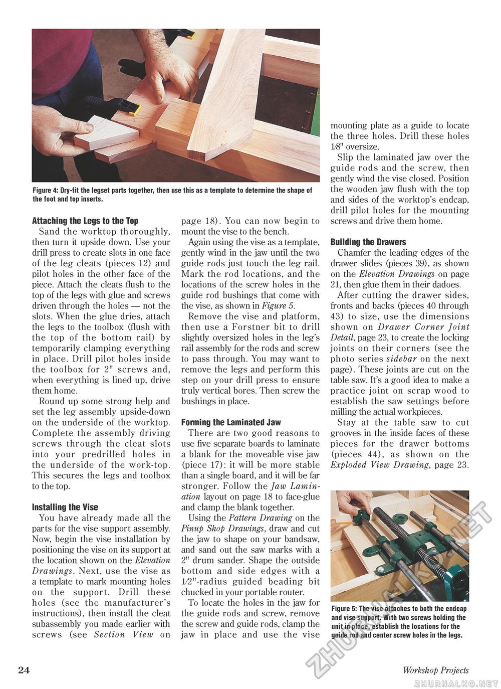
Figure 4: Dry-fit the legset parts together, then use this as a template to determine the shape of the foot and top inserts. Attaching the Legs to the Top Sand the worktop thoroughly, then turn it upside down. Use your drill press to create slots in one face of the leg cleats (pieces 12) and pilot holes in the other face of the piece. Attach the cleats flush to the top of the legs with glue and screws driven through the holes — not the slots. When the glue dries, attach the legs to the toolbox (flush with the top of the bottom rail) by temporarily clamping everything in place. Drill pilot holes inside the toolbox for 2" screws and, when everything is lined up, drive them home. Round up some strong help and set the leg assembly upside-down on the underside of the worktop. Complete the assembly driving screws through the cleat slots into your predrilled holes in the underside of the work-top. This secures the legs and toolbox to the top. Installing the Vise You have already made all the parts for the vise support assembly. Now, begin the vise installation by positioning the vise on its support at the location shown on the Elevation Drawings. Next, use the vise as a template to mark mounting holes on the support. Drill these holes (see the manufacturer's instructions), then install the cleat subassembly you made earlier with screws (see Section View on page 18). You can now begin to mount the vise to the bench. Again using the vise as a template, gently wind in the jaw until the two guide rods just touch the leg rail. Mark the rod locations, and the locations of the screw holes in the guide rod bushings that come with the vise, as shown in Figure 5. Remove the vise and platform, then use a Forstner bit to drill slightly oversized holes in the leg's rail assembly for the rods and screw to pass through. You may want to remove the legs and perform this step on your drill press to ensure truly vertical bores. Then screw the bushings in place. Forming the Laminated Jaw There are two good reasons to use five separate boards to laminate a blank for the moveable vise jaw (piece 17): it will be more stable than a single board, and it will be far stronger. Follow the Jaw Lamination layout on page 18 to face-glue and clamp the blank together. Using the Pattern Drawing on the Pinup Shop Drawings, draw and cut the jaw to shape on your bandsaw, and sand out the saw marks with a 2" drum sander. Shape the outside bottom and side edges with a 1/2"-radius guided beading bit chucked in your portable router. To locate the holes in the jaw for the guide rods and screw, remove the screw and guide rods, clamp the jaw in place and use the vise mounting plate as a guide to locate the three holes. Drill these holes 1/8" oversize. Slip the laminated jaw over the guide rods and the screw, then gently wind the vise closed. Position the wooden jaw flush with the top and sides of the worktop's endcap, drill pilot holes for the mounting screws and drive them home. Building the Drawers Chamfer the leading edges of the drawer slides (pieces 39), as shown on the Elevation Drawings on page 21, then glue them in their dadoes. After cutting the drawer sides, fronts and backs (pieces 40 through 43) to size, use the dimensions shown on Drawer Corner Joint Detail, page 23, to create the locking joints on their corners (see the photo series sidebar on the next page). These joints are cut on the table saw. It's a good idea to make a practice joint on scrap wood to establish the saw settings before milling the actual workpieces. Stay at the table saw to cut grooves in the inside faces of these pieces for the drawer bottoms (pieces 44), as shown on the Exploded View Drawing, page 23. Figure 5: The vise attaches to both the endcap and vise support. With two screws holding the unit in place, establish the locations for the guide rod and center screw holes in the legs. 24 Workshop Projects |


