Creative Woodworks & crafts 1998-09, страница 62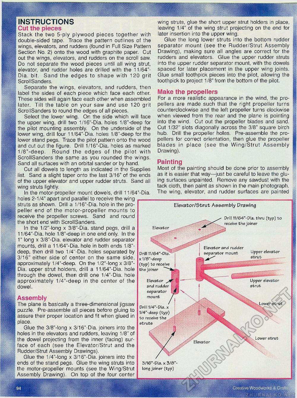
Elevator INSTRUCTIONS Cut the pieces Stack the two 5-ply plywood pieces together with double-sided tape. Trace the pattern outlines of the wings, elevators, and rudders (found in Full Size Pattern Section No. 2) onto the wood with graphite paper. Cut out the wings, elevators, and rudders on the scroll saw. Do not separate the wood pieces until all wing strut, elevator, and rudder holes are drilled with the 11/64"-Dia. bit. Sand the edges to shape with 120 grit ScrollSanders. Separate the wings, elevators,, and rudders, then label the sides of each piece which face each other. These sides will again face each other when assembled later. Tilt the table on your saw and use 120 grit ScrollSanders to round the edges of all pieces. Select the lower wing. On the side which will face the upper wing, drill two 1/16'-Dia. holes 1/8"-deep for the pilot mounting assembly. On the underside of the lower wing, drill four 11/64"-Dia. holes 1/8 '-deep for the lower stand pegs. Trace the pilot pattern onto the wood and cut out the figure. Drill 1/16"-Dia. holes as marked 1/8"-deep. Round the edges of the pilot with ScrollSanders the same as you rounded the wings. Sand all surfaces with an orbital sander or by hand. Cut all dowels to length as indicated in the Supplies list. Sand a slight taper onto the last 3/16" of the ends of the upper elevator and upper rudder struts. Sand all wing struts lightly. In the motor-propeller mount dowels, drill 11/64"-Dia. holes 2-1/4" apart and parallel to receive the wing struts as shown. Drill a 1/16"-Dia. hole in the propeller end of the motor-propeller mounts to receive the propeller screws. Sand and round the short end with ScrollSanders. In the 1/2"-long x 3/8"-Dia. stand pegs, drill a 11/64"-Dia. hole 1/8"-deep in one end only. In the 1" long x 3/8"-Dia. elevator and rudder separator mounts, drill a 11 /64 -Dia. hole in both ends 1/8"-deep, then drill two 1/4"-Dia. holes separated by 3/16" either side of center on the same side, approximately 1/4"-deep. On the 1/2"-long x 3/8"-Dia. upper strut holders, drill a 11/64"-Dia. hole through the dowel, then drill one 1/4"-Dia. hole approximately 1/4"-deep in the center of the dowel. wing struts, glue the short upper strut holders in place, leaving 1/4" of the wing strut projecting on the end for later insertion into the upper wing. Glue the long lower struts into the bottom rudder separator mount (see the Rudder/Strut Assembly Drawing), making sure all angles are correct for the rudders and elevators. Glue the upper rudder struts into the upper rudder separator mount, with the dowels spaced for later placement in the upper wing joints. Glue small toothpick pieces into the pilot, allowing the toothpick to project 1/8" from the bottom of the pilot. Make the propellers For a more realistic appearance in the wind, the propellers are made such that the right propeller turns counterclockwise and the left propeller turns clockwise when viewed from the rear and the plane is pointing into the wind. Cut out the propeller blades and sand. Cut 1/32" slots diagonally across the 3/8" square birch hub. Drill the propeller holes. Pre-assemble the propellers for correct orientation, then glue the propeller blades in place (see the Wing/Strut Assembly Drawing). Painting Most of the painting should be done prior to assembly as it is easier that way—just be careful to leave the gluing surfaces unpainted. Remove any sawdust with the tack cloth, then paint as shown in the main photograph. The wing, elevator, and rudder surfaces are painted Assembly The plane is basically a three-dimensional jigsaw puzzle. Pre-assemble all pieces before gluing to assure their proper location and fit when glued in place. Glue the 3/8"-long x 3/16"-Dia. joiners into the holes in the elevators and rudders, leaving 1/8" of the dowel projecting from the inner (facing) surface of each (see the Elevator/Strut and the Rudder/Strut Assembly Drawings). Glue the 1/4"-long x 3/16"-Dia. joiners into the ends of the stand pegs. Glue the wing struts into the motor-propeller mounts (see the Wing/Strut Assembly Drawing). On top of the four center Elevator/Strut Assembly Drawing Elevator Drill x 1/&"-deep (typ) to receive the joiner Elevator and rudder separator mount Drill 11/64"-Dia. thru (typ) to receive the joiner Upper elevator strut Elevator and rudder separator mount Upper elevator strut Lower strut Drill 1/4"-Dia. x 1/4"-deep (typ) to receive the struts Lower strut 3/16"-Dia. x 3/0"-long joiner (typ) |


