Popular Woodworking 2000-10 № 117, страница 26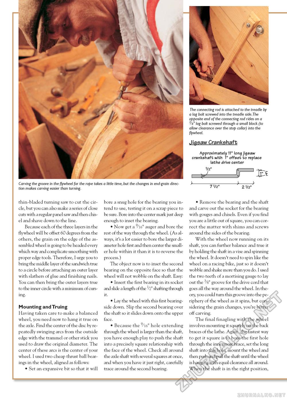
The connecting rod is attached to the treadle by a lag bolt screwed into the treadle side.The opposite end of the connecting rod rides on a 3/8" lag bolt screwed through a small block (to allow clearance over the stop collar) into the flywheel. Jigsaw Crankshaft Approximately 11" long jigsaw crankshaft with 1" offset to replace lathe drive center 1/2" Carving the groove in the flywheel for the rope takes a little time, but the changes in end-grain direction makes carving easier than turning. Bc 7 1/2" 2 1/2" thin-bladed turning saw to cut the circle, but you can also make a series of close cuts with a regular panel saw and then chisel and shave down to the line. Because each of the three layers in the flywheel will be offset 60 degrees from the others, the grain on the edge of the assembled wheel is going to be headed every which way and complicate smoothing with proper edge tools. Therefore, I urge you to bring the middle layer of the sandwich true to a circle before attaching an outer layer with slathers of glue and finishing nails. You can then bring the outer layers true to the inner circle with a minimum of cursing. Mounting and Truing Having taken care to make a balanced wheel, you need now to hang it true on the axle. Find the center of the disc by repeatedly swinging arcs from the outside edge with the trammel or other stick you used to draw the original diameter. The center of these arcs is the center of your wheel. I used two cheap thrust ball bearings in the wheel, aligned as follows: • Set an expansive bit so that it will bore a snug hole for the bearing you intend to use, testing it on a scrap piece to be sure. Bore into the center mark just deep enough to inset the bearing. • Now get a 9/l6" auger and bore the rest of the way through the wheel. (As always, it's a lot easier to bore the larger diameter hole first and then center the smaller hole within it than it is to reverse the process.) The object now is to inset the second bearing on the opposite face so that the wheel will not wobble on the shaft. Easy: • Insert the first bearing in its socket and slide a length of the 1/2" shafting through it. • Lay the wheel with this first bearing-side down. Slip the second bearing over the shaft so it slides down onto the upper face. • Because the 9/l6" hole extending through the wheel is larger than the shaft, you have enough play to push the shaft into a precisely square relationship with the face of the wheel. Check all around the axle shaft with several squares at once, and when you have it just right, carefully trace around the second bearing. • Remove the bearing and the shaft and carve out the socket for the bearing with gouges and chisels. Even if you find you are a little out of square, you can correct the matter with shims and screws around the sides of the bearing. With the wheel now running on its shaft, you can further balance and true it by holding the shaft in a vise and spinning the wheel. It doesn't need to spin like the wheel on a racing bike, just so it doesn't wobble and shake more than you do. I used the two teeth of a mortising gauge to lay out the 3/8" groove for the drive cord that goes all the way around the wheel. In theory, you could turn this groove into the periphery of the wheel as it spins, but considering the grain changes, you're better off carving. The final finagling with the wheel involves mounting it squarely on the back braces of the lathe. Again, the fastest way to get it square is to bore the first hole through the innermost brace, set the long shaft into this hole, mount the wheel and then push and pull the shaft until the wheel is hanging with equal clearance all around. When the shaft is in the right position, |


