Popular Woodworking 2000-10 № 117, страница 27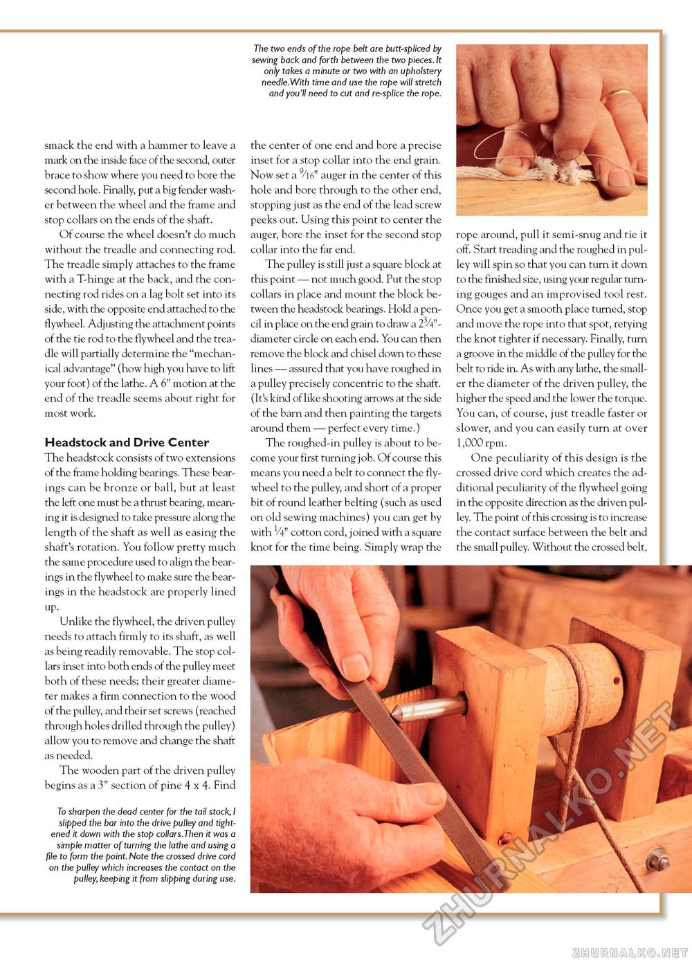
smack the end with a hammer to leave a mark on the inside face of the second, outer brace to show where you need to bore the second hole. Finally, put a big fender washer between the wheel and the frame and stop collars on the ends of the shaft. Of course the wheel doesn't do much without the treadle and connecting rod. The treadle simply attaches to the frame with a T-hinge at the back, and the connecting rod rides on a lag bolt set into its side, with the opposite end attached to the flywheel. Adjusting the attachment points of the tie rod to the flywheel and the treadle will partially determine the "mechanical advantage" (how high you have to lift your foot) of the lathe. A 6" motion at the end of the treadle seems about right for most work. Headstock and Drive Center The headstock consists of two extensions of the frame holding bearings. These bearings can be bronze or ball, but at least the left one must be a thrust bearing, meaning it is designed to take pressure along the length of the shaft as well as easing the shaft's rotation. You follow pretty much the same procedure used to align the bearings in the flywheel to make sure the bearings in the headstock are properly lined up. Unlike the flywheel, the driven pulley needs to attach firmly to its shaft, as well as being readily removable. The stop collars inset into both ends of the pulley meet both of these needs; their greater diameter makes a firm connection to the wood of the pulley, and their set screws (reached through holes drilled through the pulley) allow you to remove and change the shaft as needed. The wooden part of the driven pulley begins as a 3" section of pine 4 x 4. Find To sharpen the dead center for the tail stock, I slipped the bar into the drive pulley and tightened it down with the stop collars.Then it was a simple matter of turning the lathe and using a file to form the point. Note the crossed drive cord on the pulley which increases the contact on the pulley, keeping it from slipping during use. The two ends of the rope belt are butt-spliced by sewing back and forth between the two pieces. It only takes a minute or two with an upholstery needle.With time and use the rope will stretch and you'll need to cut and re-splice the rope. the center of one end and bore a precise inset for a stop collar into the end grain. Now set a 9/l6" auger in the center of this hole and bore through to the other end, stopping just as the end of the lead screw peeks out. Using this point to center the auger, bore the inset for the second stop collar into the far end. The pulley is still just a square block at this point — not much good. Put the stop collars in place and mount the block between the headstock bearings. Hold a pencil in place on the end grain to draw a 23/4"-diameter circle on each end. You can then remove the block and chisel down to these lines — assured that you have roughed in a pulley precisely concentric to the shaft. (It's kind of like shooting arrows at the side of the barn and then painting the targets around them — perfect every time.) The roughed-in pulley is about to become your first turning job. Of course this means you need a belt to connect the flywheel to the pulley, and short of a proper bit of round leather belting (such as used on old sewing machines) you can get by with V4" cotton cord, joined with a square knot for the time being. Simply wrap the rope around, pull it semi-snug and tie it off. Start treading and the roughed in pulley will spin so that you can turn it down to the finished size, using your regular turning gouges and an improvised tool rest. Once you get a smooth place turned, stop and move the rope into that spot, retying the knot tighter if necessary. Finally, turn a groove in the middle of the pulley for the belt to ride in. As with any lathe, the smaller the diameter of the driven pulley, the higher the speed and the lower the torque. You can, of course, just treadle faster or slower, and you can easily turn at over 1,000 rpm. One peculiarity of this design is the crossed drive cord which creates the additional peculiarity of the flywheel going in the opposite direction as the driven pulley. The point of this crossing is to increase the contact surface between the belt and the small pulley. Without the crossed belt, |


