Popular Woodworking 2004-04 № 140, страница 78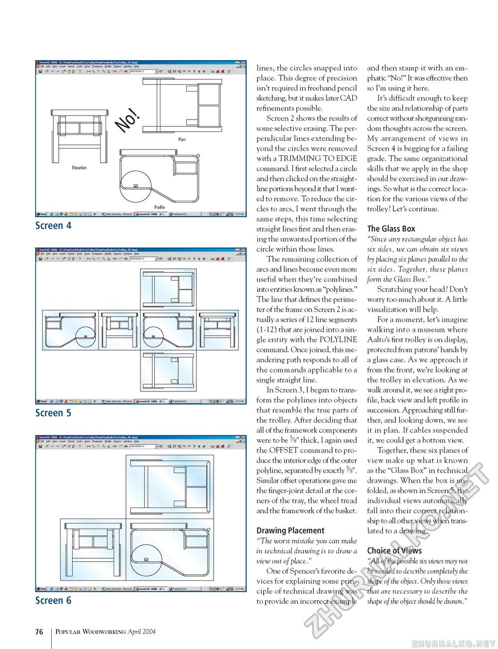
y L', U ■ I > inns*. r jf.—- Screen 4 Screen 5 Screen 6 lines, the circles snapped into place. This degree of precision isn't required in freehand pencil sketching, but it makes later CAD refinements possible. Screen 2 shows the results of some selective erasing. The perpendicular lines extending beyond the circles were removed with a TRIMMING TO EDGE command. I first selected a circle and then clicked on the straight-line portions beyond it that I wanted to remove. To reduce the circles to arcs, I went through the same steps, this time selecting straight lines first and then erasing the unwanted portion of the circle within those lines. The remaining collection of arcs and lines become even more useful when they're combined into entities known as "polylines." The line that defines the perimeter of the frame on Screen 2 is actually a series of 12 line segments (1-12) that are joined into a single entity with the POLYLINE command. Once joined, this meandering path responds to all of the commands applicable to a single straight line. In Screen 3, I began to transform the polylines into objects that resemble the true parts of the trolley. After deciding that all of the framework components were to be ^s" thick, I again used the OFFSET command to produce the interior edge of the outer polyline, separated by exactly ^S". Similar offset operations gave me the finger-joint detail at the corners of the tray, the wheel tread and the framework of the basket. Drawing Placement "The worst mistake you can make in technical drawing is to draw a view out of place." One of Spencer's favorite devices for explaining some principle of technical drawing was to provide an incorrect example and then stamp it with an emphatic "No!" It was effective then so I'm using it here. It's difficult enough to keep the size and relationship of parts correct without shotgunning random thoughts across the screen. My arrangement of views in Screen 4 is begging for a failing grade. The same organizational skills that we apply in the shop should be exercised in our drawings. So what is the correct location for the various views of the trolley? Let's continue. The Glass Box "Since any rectangular object has six sides, we can obtain six views by placing six planes parallel to the six sides. Together, these planes form the Glass Box." Scratching your head? Don't worry too much about it. A little visualization will help. For a moment, let's imagine walking into a museum where Aalto's first trolley is on display, protected from patrons' hands by a glass case. As we approach it from the front, we're looking at the trolley in elevation. As we walk around it, we see a right profile, back view and left profile in succession. Approaching still further, and looking down, we see it in plan. If cables suspended it, we could get a bottom view. Together, these six planes of view make up what is known as the "Glass Box" in technical drawings. When the box is unfolded, as shown in Screen 5, the individual views automatically fall into their correct relationship to all other views when translated to a drawing. Choice of Views "All of the possible six views may not be needed to describe completely the shape of the object. Only those views that are necessary to describe the shape of the object should be drawn." Profile 76 Popular Woodworking April 2004 |


