Popular Woodworking 2004-04 № 140, страница 79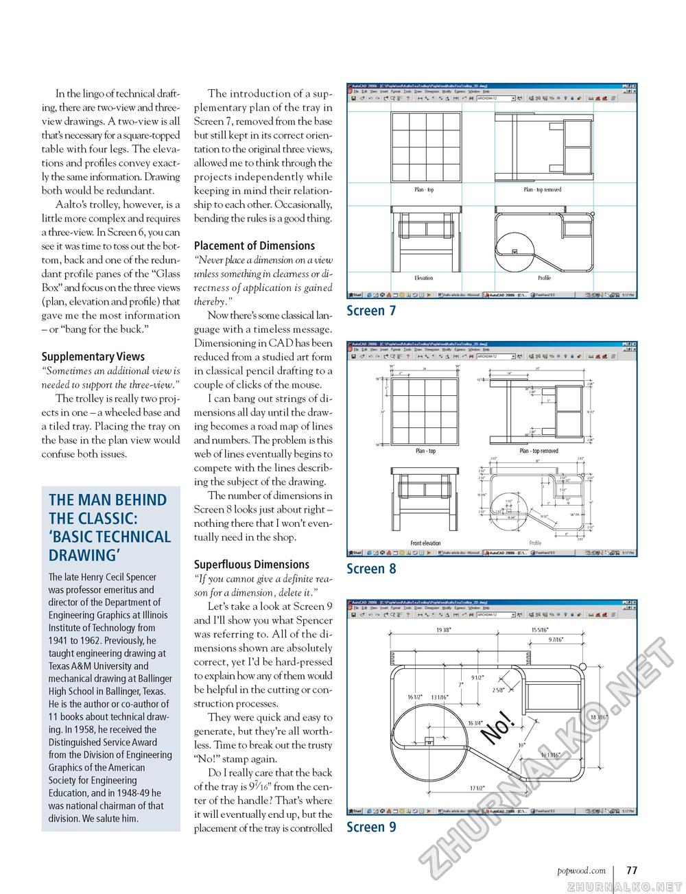
In the lingo of technical drafting, there are two-view and three-view drawings. A two-view is all that's necessary for a square-topped table with four legs. The elevations and profiles convey exactly the same information. Drawing both would be redundant. Aalto's trolley, however, is a little more complex and requires a three-view. In Screen 6, you can see it was time to toss out the bottom, back and one of the redundant profile panes of the "Glass Box" and focus on the three views (plan, elevation and profile) that gave me the most information - or "bang for the buck." Supplementary Views "Sometimes an additional view is needed to support the three-view." The trolley is really two projects in one - a wheeled base and a tiled tray. Placing the tray on the base in the plan view would confuse both issues. THE MAN BEHIND THE CLASSIC: 'BASIC TECHNICAL DRAWING' The late Henry Cecil Spencer was professor emeritus and director of the Department of Engineering Graphics at Illinois Institute of Technology from 1941 to 1962. Previously, he taught engineering drawing at Texas A&M University and mechanical drawing at Ballinger High School in Ballinger, Texas. He is the author or co-author of 11 books about technical drawing. In 1958, he received the Distinguished Service Award from the Division of Engineering Graphics of the American Society for Engineering Education, and in 1948-49 he was national chairman of that division. We salute him. The introduction of a supplementary plan of the tray in Screen 7, removed from the base but still kept in its correct orientation to the original three views, allowed me to think through the projects independently while keeping in mind their relationship to each other. Occasionally, bending the rules is a good thing. Placement of Dimensions "Never place a dimension on a view unless something in clearness or directness of application is gained thereby." Now there's some classical language with a timeless message. Dimensioning in CAD has been reduced from a studied art form in classical pencil drafting to a couple of clicks of the mouse. I can bang out strings of dimensions all day until the drawing becomes a road map of lines and numbers. The problem is this web of lines eventually begins to compete with the lines describing the subject of the drawing. The number of dimensions in Screen 8 looks just about right -nothing there that I won't eventually need in the shop. Superfluous Dimensions "If you cannot give a definite reason for a dimension, delete it." Let's take a look at Screen 9 and I'll show you what Spencer was referring to. All of the dimensions shown are absolutely correct, yet I'd be hard-pressed to explain how any of them would be helpful in the cutting or construction processes. They were quick and easy to generate, but they're all worthless. Time to break out the trusty "No!" stamp again. Do I really care that the back of the tray is 97/l6" from the center of the handle? That's where it will eventually end up, but the placement of the tray is controlled t* If** I—'» It* b* ' ' ! HK- B- II-
Screen 7
i, ft iP, a Front elevation Profile J|juj«Cim Mat* ■ M~ j^gg^jK Screen 8 £ ft ^ j J4 \> J > Screen 9 popwood.com 77 |
||||||||||||||||||||||||||||||||||||||||||||||||||||||||||||||||||||||||||||||||||||||||||||||||||||||||||||||||||||||||||||||||||||||||||||||||||||||||||||||||||||


