10 - Heavy Duty Lathe Stand, страница 6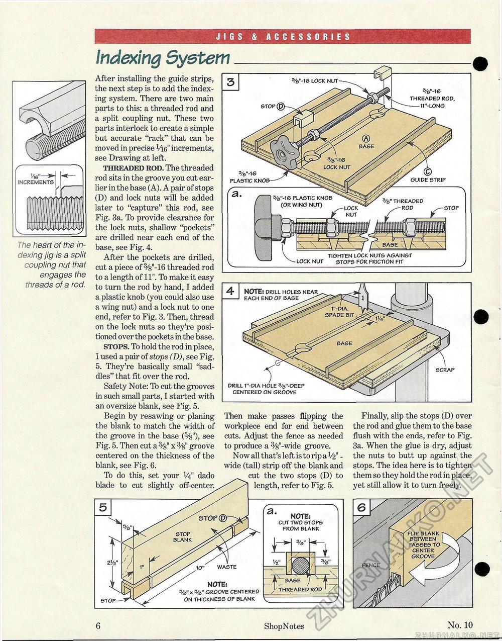
JIGS & ACCESSORIES The heart of the indexing jig is a split coupling nut that engages the threads of a rod. Indexing System DRILL 1"-DIA HOLE %"-DEEP CENTERED ON GROOVE SCRAP WASTE 4 NOTE: DRILL HOLES NEAR EACH END OF BASE After installing the guide strips, the next step is to add the indexing system. There are two main parts to this: a threaded rod and a split coupling nut. These two parts interlock to create a simple but accurate "rack" that can be moved in precise Vie," increments, see Drawing at left. threaded rod. The threaded rod sits in the groove you cut earlier in the base (A). A pair of stops (D) and lock nuts will be added later to "capture" this rod, see Fig. 3a. To provide clearance for the lock nuts, shallow "pockets" are drilled near each end of the base, see Fig. 4. After the pockets are drilled, cut a piece of 3/s"-16 threaded rod to a length of 11". To make it easy to turn the rod by hand, I added a plastic knob (you could also use a wing nut) and a lock nut to one end, refer to Fig. 3. Then, thread on the lock nuts so they're positioned over the pockets in the base. stops. To hold the rod in place, I used a pair of stops (D), see Fig. 5. They're basically small "saddles" that fit over the rod. Safety Note: To cut the grooves in such small parts, I started with an oversize blank, see Fig. 5. Begin by resawing or planing the blank to match the width of the groove in the base (5/&"), see Fig. 5. Then cut a 3/8M x groove centered on the thickness of the blank, see Fig. 6. To do this, set your V4" dado blade to cut slightly off-center. C, \ NOTE: CUT TWO STOPS FROM BLANK NOTE: 3/&" x 3/0" GROOVE CENTERED ON THICKNESS OF BLANK Then make passes flipping the workpiece end for end between cuts. Adjust the fence as needed to produce a 3/8"-wide groove. Now all that's left is to rip a V2" -wide (tall) strip off the blank and cut the two stops (D) to length, refer to Fig. 5. %"-16 THREADED ROD, 11"-LONG STOP TIGHTEN LOCK NUTS AGAINST LOCK NUT STOPS FOR FRICTION FIT %"-16 LOCK NUT %"-16 PLASTIC 3/s" THREADED STOP HJIDE STRIP s/e"-16 PLASTIC KNOB (OR WING NUT) Finally, slip the stops (D) over the rod and glue them to the base flush with the ends, refer to Fig. 3a. When the glue is dry, adjust the nuts to butt up against the stops. The idea here is to tighten them so they hold the rod in place, yet still allow it to turn freely. 6 ShopNotes No. 10 |


