10 - Heavy Duty Lathe Stand, страница 8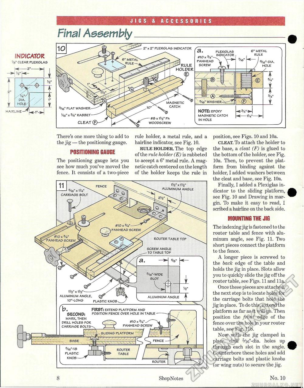
JIGS & ACCESSORIES INDICATOR V&" CLEAR PLEXIGLAS —2"- 1/2" 2" ft As' PIA. HOLE-' HAIRLINE - Va" There's one more thing to add to the jig — the positioning gauge. POSITIONING GAUGE The positioning gauge lets you see how much you've moved the fence. It consists of a two-piece rule holder, a metal rule, and a hairline indicator, see Fig. 10. rule holder. The top edge of the rule holder (E) is rabbeted to accept a 6" metal rale. A magnetic catch centered on the length of the holder keeps the rule in position, see Figs. 10 and 10a. cleat. To attach the holder to the base, a cleat (F) is glued to the bottom of the holder, see Fig. 10a. Then, to prevent the platform from binding against the holder, I added washers between the cleat and base, see Fig. 10a. Finally, I added a Plexiglas indicator to the sliding platform, see Fig. 10 and Drawing in margin. To make it easy to read, I scribed a hairline on the back side. MOUNTING THE JIG The indexing jig is fastened to the router table and fence with aluminum angle, see Fig. 11. Two short pieces connect the platform to the fence. A longer piece is screwed to the back edge of the table and holds the jig in place. Slots allow you to quickly slide the jig off the router table, see Figs. 11 and 11a. Once these pieces are attached, the next step is to locate holes for the carriage bolts that hold the jig in place. To do this, extend the platform as far as it will go. Then position the front edge of the fence over the hole in your router table, see Fig. lib. Now with the jig clamped in place, drill 5/i6"-dia. holes up through each slot in the angle. Counterbore these holes and add carriage bolts and plastic knobs (or wing nuts) to secure the jig. 8 ShopNotes No. 10 Final AssemblyPLEXIGLAS indicator mo y. 3A" PANHEAD SCREW NOTE: EPOXY MAGNETIC CATCH IN HOLE V _ 3/16" FLAT 1/,6" x 3/4" RABBET CLEAT 2" x 2" PLEXIGLAS INDICATOR RULE HOLPER 6" METAL RULE 9/I6"-DIA. HOLE 1V2" x 11/2" ALUMINUM ANGLE SCREW ANGLE TO TABLE TOP 5Ae"- WIDE SLOT V/z" x ALUMINUM ANGLE. 10"-L0NG PLASTIC KNOB ft ALUMINUM ANGLE ^- b. SECONP: MARK. THEN DRILL HOLES FOR FIRST: EXTEND PLATFORM AND POSITION FENCE OVER HOLE IN TABLE #10x3/4" ----PANHEAD SCREW |


