10 - Heavy Duty Lathe Stand, страница 7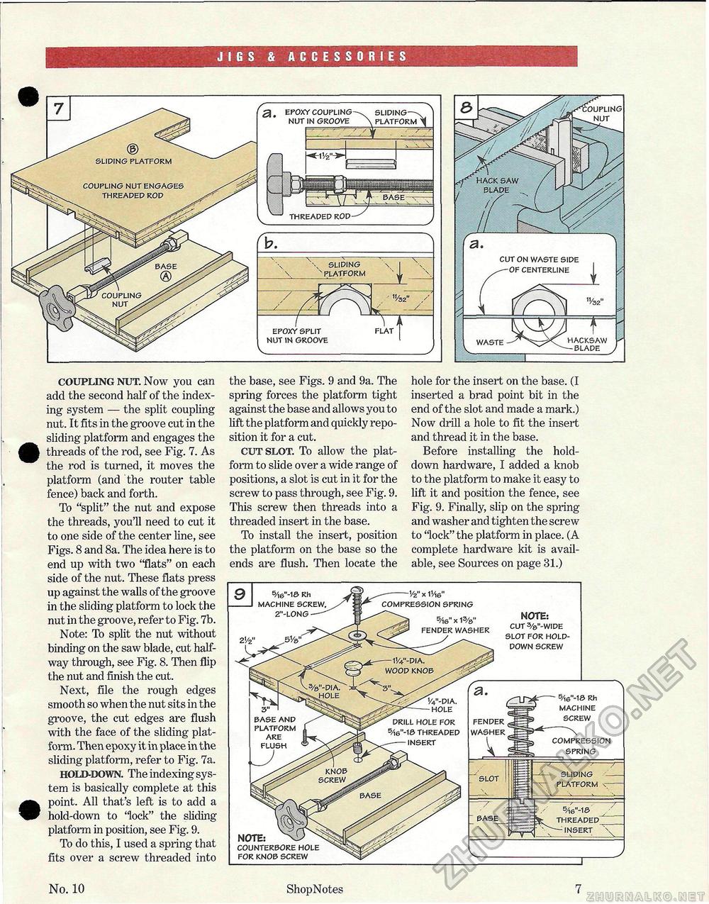
JIGS & ACCESSORIES SLIDING ' PLATFORM epoxy split nut in groove V_ 's: epoxy coupling nut in groove sliding >M>J PLATFORM waste hacksaw blade cut on waste side -of centerline coupling nut. Now you can add the second half of the indexing system — the split coupling nut. It fits in the groove cut in the sliding platform and engages the threads of the rod, see Fig. 7. As the rod is turned, it moves the platform (and the router table fence) back and forth. To "split" the nut and expose the threads, you'll need to cut it to one side of the center line, see Figs. 8 and 8a. The idea here is to end up with two "flats" on each side of the nut. These flats press up against the walls of the groove in the sliding platform to lock the nut in the groove, refer to Fig. 7b. Note: To split the nut without binding on the saw blade, cut halfway through, see Fig. 8. Then flip the nut and finish the cut. Next, file the rough edges smooth so when the nut sits in the groove, the cut edges are flush with the face of the sliding platform. Then epoxy it in place in the sliding platform, refer to Fig. 7a. hold-down. The indexing system is basically complete at this point. All that's left is to add a hold-down to "lock" the sliding platform in position, see Fig. 9. To do this, I used a spring that fits over a screw threaded into the base, see Figs. 9 and 9a. The spring forces the platform tight against the base and allows you to lift the platform and quickly reposition it for a cut. cut slot. To allow the platform to slide over a wide range of positions, a slot is cut in it for the screw to pass through, see Fig. 9. This screw then threads into a threaded insert in the base. To install the insert, position the platform on the base so the ends are flush. Then locate the hole for the insert on the base. (I inserted a brad point bit in the end of the slot and made a mark.) Now drill a hole to fit the insert and thread it in the base. Before installing the hold-down hardware, I added a knob to the platform to make it easy to lift it and position the fence, see Fig. 9. Finally, slip on the spring and washer and tighten the screw to 'lock" the platform in place. (A complete hardware kit is available, see Sources on page 31.) No. 10 ShopNotes 7 fender washer sliding - platform v- 5/i6"-1& rh machine screw compression spring slot 5Ae"-13 insert NOTE: cut 3/6"-wide slot for hold-down screw 1/4"-dia. hole drill hole for 5/i6"-16 threaded insert 5/16"-1© rh machine screw. 2"-long 1/2" x 1'/i6" compression spring 5Ae" x 15/s" fender washer base and platform flush NOTE; counterbore hole for knob screw |


