19 - Clamp Storage System, страница 19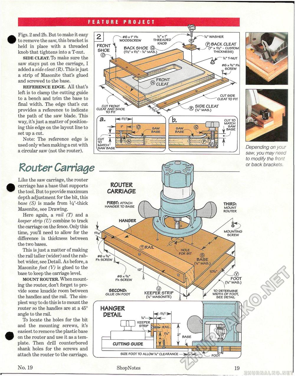
FRONT CLEAT, Figs. 2 and 2b. But to make it easy to remove the saw, this bracket is held in place with a threaded knob that tightens into a T-nut. side cleat. To make sure the saw stays put on the carnage, I added a side cleat (R). This is just a strip of Masonite that's glued and screwed to the base. reference edge. All that's left is to clamp the cutting guide to a bench and trim the base to final width. The edge that's cut provides a reference to indicate the path of the saw blade. This way, it's just a matter of positioning this edge on the layout line to set up a cut. Note: The reference edge is used only when making a cut with a circular saw (not the router). FEATURE PROJECT 1/4" WASHER F) BACK CLEAT (1" x W - CUSTOM THICKNESS) FRONT SHOE ©r^ A-" T-NUT #6 x Fh SCREW CUT SIDE CLEAT TO FIT SIDE CLEAT (!4" MAS.) CUT FRONT CLEAT AND SHOE TO FIT CUT TO MATCH SAW BASE SAW BASE SAW BASE CUT TO MATCH SAW Depending on your saw, you may need to modify the front or back brackets. No. 19 ShopNotes 19 Router Carriage FOOT Like the saw carriage, the router carriage has a base that supports the tool. But to provide maximum depth adjustment for the bit, this base (S) is made from V^'-thick Masonite, see Drawing. Here again, a rail (T) and a keeper strip (U) combine to track the carnage on the fence. Only this time, you'll need to allow for the difference in thickness between the two bases. This is just a matter of making the rail taller (wider) and the rabbet wider, see Detail. As before, a Masonite foot (V) is glued to the base to keep the carnage level. mount router When mounting the router, clon't forget to provide some knuckle room between the handles and the rail. The simplest way to do this is to mount the router so the handles are at a 45° angle to the rail. To locate the holes for the bit and the mounting screws, it's easiest to remove the plastic base on the router and use it as a template. Then drill counterbored shank holes for the screws and attach the router to the carriage. THIRD: MOUNT ROUTER MOUNTING SCREW FOOT (1/4" MAS.) TO DETERMINE WIDTH OF FOOT, SEE DETAIL BASE SIZE FOOT TO ALLOW VV CLEARANCE —• ROUTER CARRIAGE FIRST: ATTACH HANGER TO BASE (V MASONITE) HANGER DETAIL V4 -> j j~| I KEEPER W Fh SCREW SECOND: GLUE ON FOOT CUTTING GUIDE |


