19 - Clamp Storage System, страница 18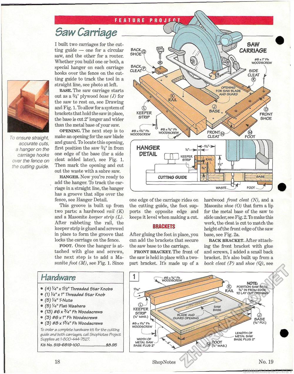
i To ensure straight, accurate cuts, a hanger on the carriage hooks over the fence on the cutting guide. BACK, SHOE SACK CLEAT OPENING^ FOR SAW BLADE V AND GUARD #6 x SA" Fh WOODSCREW FRONT, CLEAT FOOT SAW CARRIAGE #6 x 1" Fh WOODSCREW \ SIDE ) CLEAT i 9 f 5aw Carriage I built two carriages for the cutting guide — one for a circular saw, and the other for a router. Whether you build one or both, a special hanger on each carriage hooks over the fence on the cutting guide to track the tool in a straight line, see photo at left. base. The saw carriage starts out as a plywood base (J) for the saw to rest on, see Drawing and Fig. 1. To allow for a system of brackets that hold the saw in place, the base is cut 2" longer and wider than the metal base of your saw. opening. The next step is to make an opening for the saw blade and guard. To locate this opening, first position the saw in from one edge of the base (for a side cleat added later), see Fig. 1. Then mark the opening and cut out the waste with a sabre saw. hanger. Now you're ready to add the hanger. To track the carriage in a straight line, the hanger has a groove that slips over the fence, see Hanger Detail. This groove is built up from two parts: a hardwood rail (K) and a Masonite keeper strip (L). After rabbeting the rail, the keeper strip is glued and screwed in place to form the groove that locks the carriage on the fence. foot. Once the hanger is attached with glue and screws, the next step is to add a Masonite foot (M), see Fig. 1. Since ® KEEPER STRIP f #& x 1%" Fh WOODSCREW HANGER DETAIL S> FRONT SHOE CUTTING GUIDE WASTE one edge of the carriage rides on the cutting guide, the foot supports the opposite edge and keeps it level when making a cut. BRACKETS After gluing the foot in place, you can add the brackets that secure the saw base to the carriage. front bracket. The front of the saw is held in place with a two-part bracket. It's made up of a hardwood front cleat (N), and a Masonite shoe (O) that form a lip for the metal base of the saw to slide under, see Fig. 2. To make this work, the cleat is cut to match the height of the front edge of the saw base, see Fig. 2a. back bracket. After attaching the front bracket with glue and screws, I added a small back bracket. It's also built up from a back cleat (P) and shoe (Q), see Hardware • (4) V4" x IV2" Threaded Star Knobs « (1) 1/4"x 1" Threaded Star Knob ® (5) V4" T-Nuts o (5) V4" Fiat Washers © (13) #6 x 5A" Fh Woodscrews • (3) #6 x 1" Fh Wood&crews © (3) #8 x P/4" Fh Woodscrews To order a complete hardware kit for the cutting guide and both carriages, call ShopNotes Froject Supplies at 1-300-444-7527. Kit No. S19-6&19-100...........................$3.95 NOTE: POSITION SAW BASE V IN FROM EDGE TO LAY OUT OPENING WIDTH OF METAL SAW BASE PLUS 2" (3/4" PLY.) KEEPER STRIP ('A" MAS.) #& x P/4" Fh WOODSCREW FOOT (!4" MAS.) LENGTH OF METAL SAW BASE PLUS 2" 18 ShopNotes No. 19 |


