36 - Miter Trimmer, страница 18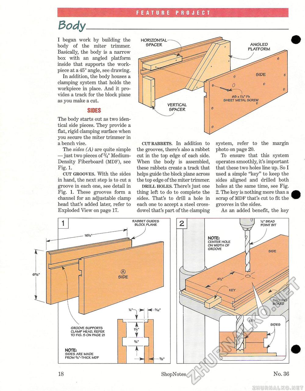
FEATURE PROJECT 3ody. I began work by building the body of the miter trimmer. Basically, the body is a narrow box with an angled platform inside that supports the work-piece at a 45° angle, see drawing. In addition, the body houses a clamping system that holds the workpiece in place. And it provides a track for the block plane as you make a cut. SIDES The body starts out as two identical side pieces. They provide a flat, rigid clamping surface when you secure the miter trimmer in a bench vise. The sides (A) are quite simple — just two pieces of Medium-Density Fiberboard (MDF), see Fig. 1. cut grooves. With the sides in hand, the next step is to cut a groove in each one, see detail in Fig. 1. These grooves form a channel for an adjustable clamp head that's added later, refer to Exploded View on page 17. HORIZONTAL SPACER cut rabbets. In addition to the grooves, there's also a rabbet cut in the top edge of each side. When the body is assembled, these rabbets create a track that helps guide the block plane across the top edge of the miter trimmer. drill holes. There's just one thing left to do to complete the sides. That's to drill a hole in each one to accept a steel cross-dowel that's part of the clamping system, refer to the margin photo on page 20. To ensure that this system operates smoothly, it's important that these two holes line up. So I used a simple "key" to keep the sides aligned and drilled both holes at the same time, see Fig. 2. The key is nothing more than a scrap of MDF that's cut to fit the grooves in the sides. As an added benefit, the key 6%" NOTE: sides are made from 3/4"-thick mdf NOTE: center hole on width of groove vz" brad point bit backing board side 18 ShopNotes No. 36 |


