36 - Miter Trimmer, страница 21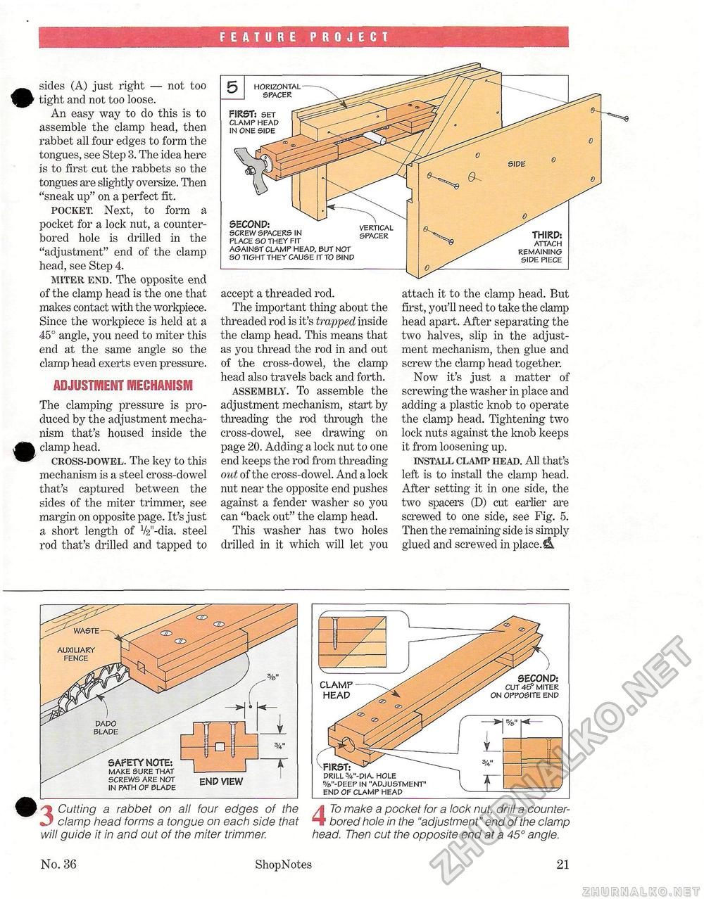
FEATURE PROJECT sides (A) just right — not too f^} tight and not too loose. An easy way to do this is to assemble the clamp head, then rabbet all four edges to form the tongues, see Step 3. The idea here is to first cut the rabbets so the tongues are slightly oversize. Then "sneak up" on a perfect fit. pocket. Next, to form a pocket for a lock nut, a counter-bored hole is drilled in the "adjustment" end of the clamp head, see Step 4. miter end. The opposite end of the clamp head is the one that makes contact with the workpiece. Since the workpiece is held at a 45° angle, you need to miter this end at the same angle so the clamp head exerts even pressure. ADJUSTMENT mechanism The clamping pressure is produced by the adjustment mechanism that's housed inside the ^fe clamp head. ^^ cross-dowel. The key to this mechanism is a steel cross-dowel that's captured between the sides of the miter trimmer, see margin on opposite page. It's just a short length of V2M-dia. steel rod that's drilled and tapped to accept a threaded rod. The important thing about the threaded rod is it's trapped inside the clamp head. This means that as you thread the rod in and out of the cross-dowel, the clamp head also travels back and forth. assembly. To assemble the adjustment mechanism, start by threading the rod through the cross-dowel, see drawing on page 20. Adding a lock nut to one end keeps the rod from threading out of the cross-dowel. And a lock nut near the opposite end pushes against a fender washer so you can "back out" the clamp head. This washer has two holes drilled in it which wall let you attach it to the clamp head. But first, you'll need to take the clamp head apart. After separating the two halves, slip in the adjustment mechanism, then glue and screw the clamp head together. Now it's just a matter of screwing the washer in place and adding a plastic knob to operate the clamp head. Tightening two lock nuts against the knob keeps it from loosening up. install clamp head. AH that's left is to install the clamp head. After setting it in one side, the two spacers (D) cut earlier are screwed to one side, see Fig. 5. Then the remaining side is simply glued and screwed in placed SECOND: vertical screw spacers in cparpi? placesotheyfit spacek against clamp heap, but not so tight they cause it to bind THIRD: attach remaining side piece horizontal spacer FIRST: set clamp head in one side 0 3 Cutting a rabbet on all four edges of the clamp head forms a tongue on each side that will guide it in and out of the miter trimmer. END VIEW auxiliary fence blade SAFETY NOTE*. make sure that screws are not in path of blade
CLAMP HEAD SECOND: cut 46p miter on opposite end CLAMP HEAD drill %"-dla. hole %"-deep in "adjustment" end of clamp head 4 To make a pocket for a lock nut, drill a counter-bored hole in the "adjustment" end of the clamp head. Then cut the opposite end at a 45° angle. No. 36 ShopNotes 21 |
||||||||


