47 - Build Your Own Mortising Machine , страница 21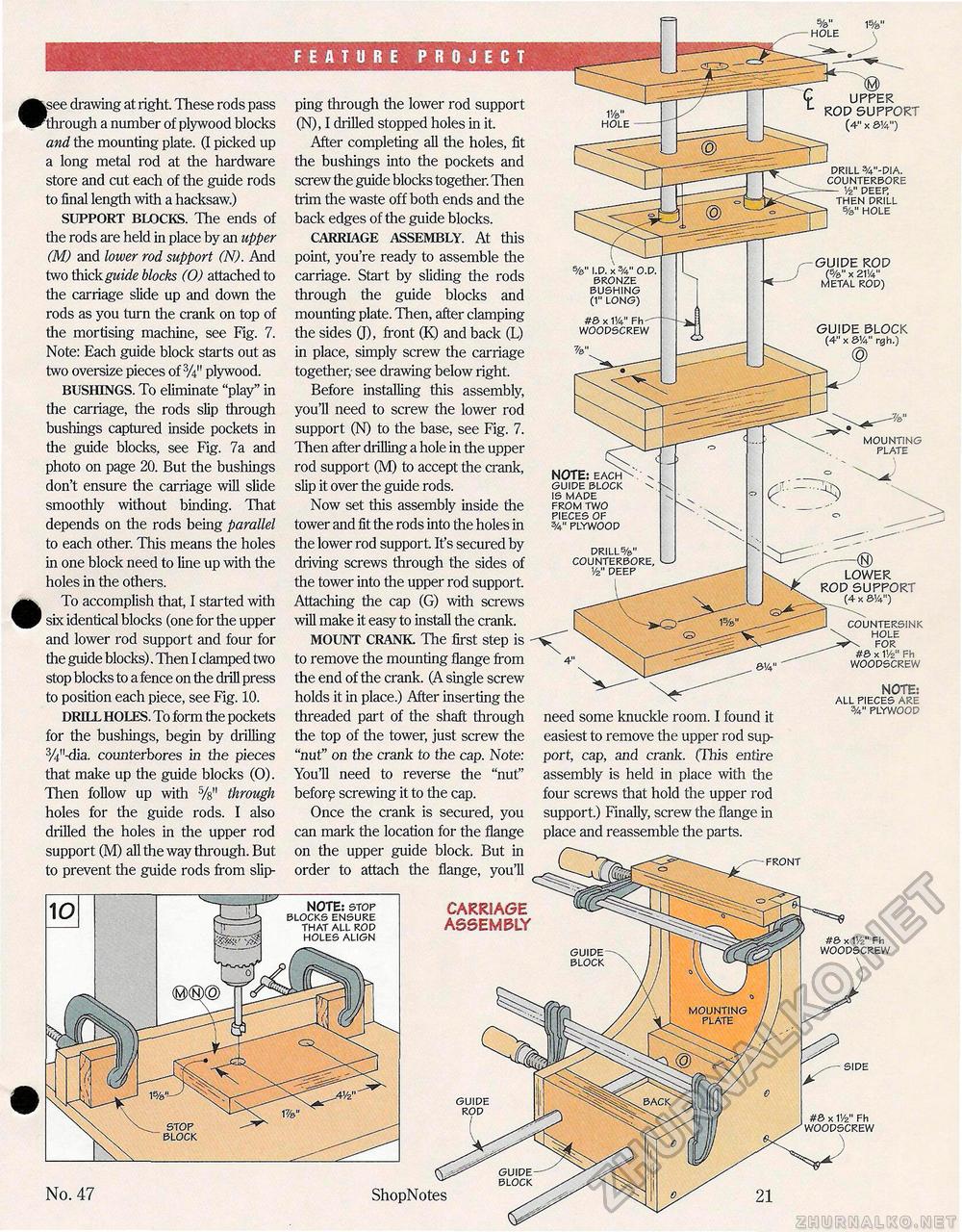
|see drawing at right. These rods pass through a number of plywood blocks and the mounting plate. (I picked up a long metal rod at the hardware store and cut each of the guide rods to final length with a hacksaw.) SUPPORT BLOCKS. The ends of the rods are held in place by an upper (M) and lower rod support (N). And two thick guide blocks (0) attached to the carriage slide up and down the rods as you turn the crank on top of the mortising machine, see Fig. 7. Note: Each guide block starts out as two oversize pieces of plywood. BUSHINGS. To eliminate "play" in the carriage, the rods slip through bushings captured inside pockets in the guide blocks, see Fig. 7a and photo on page 20. But the bushings don't ensure the carriage will slide smoothly without binding. That depends on the rods being parallel to each other. This means the holes in one block need to line up with the holes in the others. To accomplish that, I started with six identical blocks (one for the upper and lower rod support and four for the guide blocks). Then I clamped two stop blocks to a fence on the drill press to position each piece, see Fig. 10. DRILL HOLES. To form the pockets for the bushings, begin by drilling 3/i"-dia. counterbores in the pieces that make up the guide blocks (0). Then follow up with 5/s" through holes for the guide rods. I also drilled the holes in the upper rod support (M) all the way through. But to prevent the guide rods from slip FEATURE PROJECT ping through the lower rod support (N), I drilled stopped holes in it. After completing all the holes, fit the bushings into the pockets and screw the guide blocks together. Then trim the waste off both ends and the back edges of the guide blocks. CARRIAGE ASSEMBLY. At this point, you're ready to assemble the carriage. Start by sliding the rods through the guide blocks and mounting plate. Then, after clamping the sides 0), front (K) and back (L) in place, simply screw the carriage together,- see drawing below right. Before installing this assembly, you'll need to screw the lower rod support (N) to the base, see Fig. 7. Then after drilling a hole in the upper rod support (M) to accept the crank, slip it over the guide rods. Now set this assembly inside the tower and fit the rods into the holes in the lower rod support It's secured by driving screws through the sides of the tower into the upper rod support Attaching the cap (G) with screws will make it easy to install the crank. MOUNT CRANK The first step is to remove the mounting flange from the end of the crank. (A single screw holds it in place.) After inserting the threaded part of the shaft through the top of the tower, just screw the "nut" on the crank to the cap. Note: You'll need to reverse the "nut" before screwing it to the cap. Once the crank is secured, you can mark the location for the flange on the upper guide block. But in order to attach the flange, you'll CARRIAGE ASSEMBLY need some knuckle room. I found it easiest to remove the upper rod support, cap, and crank. (This entire assembly is held in place with the four screws that hold the upper rod support.) Finally, screw the flange in place and reassemble the parts. COUNTERSINK HOLE FOR #6 x V/z" Fh WOODSCREW NOTE: ALL PIECES ARE PLYWOOD FRONT #3 x V/z" Fh WOODSCREW No. 47 ShopNotes 21 SIDE #3 X v/z" Fh WOODSCREW \ y |


