47 - Build Your Own Mortising Machine , страница 23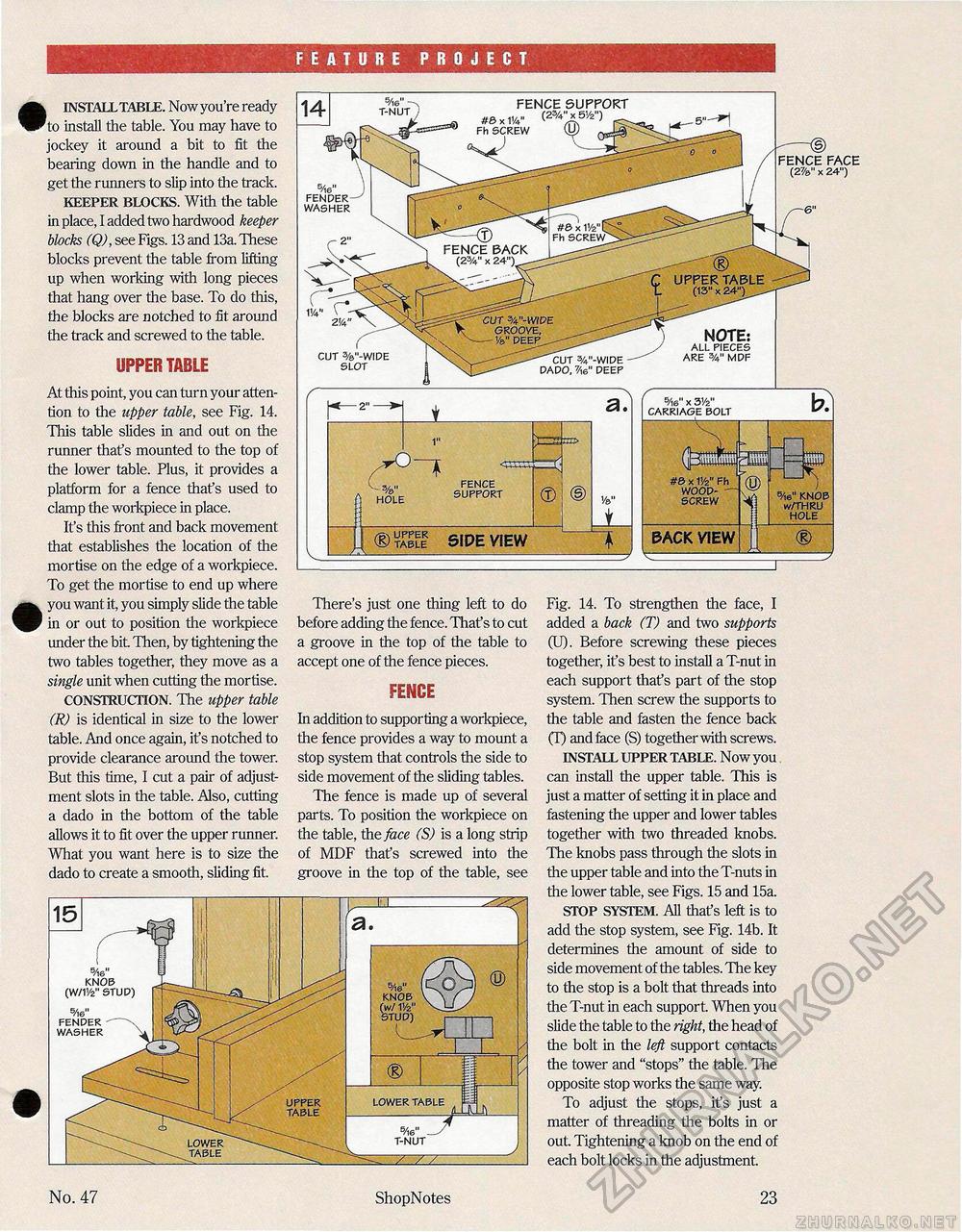
FEATURE PROJECT k INSTALL TABLE. Now you're ready 'to install the table. You may have to jockey it around a bit to fit the bearing down in the handle and to get the runners to slip into the track. KEEPER BLOCKS. With the table in place, I added two hardwood keeper blocks (Q), see Figs. 13 and 13a These blocks prevent the table from lifting up when working with long pieces that hang over the base. To do this, the blocks are notched to fit around the track and screwed to the table. UPPER TABLE At this point, you can turn your attention to the upper table, see Fig. 14. This table slides in and out on the runner that's mounted to the top of the lower table. Plus, it provides a platform for a fence that's used to clamp the workpiece in place. It's this front and back movement that establishes the location of the mortise on the edge of a workpiece. To get the mortise to end up where you want it, you simply slide the table in or out to position the workpiece under the bit Then, by tightening the two tables together, they move as a single unit when cutting the mortise. CONSTRUCTION. The upper table (R) is identical in size to the lower table. And once again, it's notched to provide clearance around the tower. But this time, I cut a pair of adjustment slots in the table. Also, cutting a dado in the bottom of the table allows it to fit over the upper runner. What you want here is to size the dado to create a smooth, sliding fit. There's just one thing left to do before adding the fence. That's to cut a groove in the top of the table to accept one of the fence pieces. FENCE In addition to supporting a workpiece, the fence provides a way to mount a stop system that controls the side to side movement of the sliding tables. The fence is made up of several parts. To position the workpiece on the table, the face (S) is a long strip of MDF that's screwed into the groove in the top of the table, see Fig. 14. To strengthen the face, I added a back (T) and two supports (U). Before screwing these pieces together, it's best to install a T-nut in each support that's part of the stop system. Then screw the supports to the table and fasten the fence back (T) and face (S) together with screws. INSTALL UPPER TABLE. Now you can install the upper table. This is just a matter of setting it in place and fastening the upper and lower tables together with two threaded knobs. The knobs pass through the slots in the upper table and into the T-nuts in the lower table, see Figs. 15 and 15a. STOP SYSTEM. All that's left is to add the stop system, see Fig. 14b. It determines the amount of side to side movement of the tables. The key to the stop is a bolt that threads into the T-nut in each support. When you slide the table to the right, the head of the bolt in the left support contacts the tower and "stops" the table. The opposite stop works the same way. To adjust the stops, it's just a matter of threading the bolts in or out Tightening a knob on the end of each bolt locks in the adjustment. Fh SCREW fence back (2W x 24") _ upper table (13" x 24")^ CUT W-WIPE GROOVE, — Ve" DEEP , note: ALL PIECES ARE %" MDF CUT 3/4"-WIDE DADO, 7Ae" DEEP fence support #& x 114" (2^51/2") FENDER WASHER -—d> fence face (2%" x 24") CUT %"-WIDE SLOT 5Ae" x 3Vz" CARRIAGE BOLT pack view v — #& x V/z" Fh WOOD-SCREW HOLE FENCE _ SUPPORT (J) €> table side view LOWER TABLE S/16" -T-NUT UPPER TABLE / // : ShopNotes No. 47 5Ae" KNOB (W/11/2" STUD) 5Ae" FENDER WASHER |


