47 - Build Your Own Mortising Machine , страница 19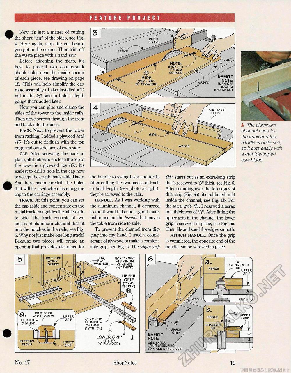
FEATURE PROJECT • Now it's just a matter of cutting the short "leg" of the sides, see Fig. 4. Here again, stop the cut before you get to the corner. Then trim off the waste piece with a hand saw. Before attaching the sides, it's best to predrill two countersunk shank holes near the inside corner of each piece, see drawing on page 18. (This will help simplify the carriage assembly.) I also installed a T-nut in the left side to hold a depth gauge that's added later. Now you can glue and clamp the sides of the tower to the inside rails. Then drive screws through the front and back into the sides. BACK Next, to prevent the tower from racking, I added a plywood back (F). It's cut to fit flush with the top edge and outside face of each side. CAP. After screwing the back in place, all it takes to enclose the top of the tower is a plywood cap (G). It's easiest to drill a hole in the cap now to accept the crank thaf s added later. And here again, predrill the holes that will be used when fastening the cap to the carriage assembly. TRACK At this point, you can set the cap aside and concentrate on the metal track that guides the tables side to side. The track consists of two pieces of aluminum channel that fit into the notches in the rails, see Fig. 5. Why not just make one long track? Because two pieces will create an opening that provides clearance for the handle to swing back and forth. After cutting the two pieces of track to final length (see photo at right), they're screwed to the rails. HANDLE. As I was working with the aluminum channel, it occurred to me it would also be a good material to use for the handle that moves the table from side to side. To prevent the channel from digging into my hand, I used a couple scraps of plywood to make a comfortable grip, see Fig. 5. The upper grip (H) starts out as an extra-long strip that's resawed to thick, see Fig. 6. After rounding over the top edges of this strip (Fig. 6a), ifs rabbeted to fit inside the channel, see Fig. 6b. For the lower grip (I), I resawed a scrap to a thickness of W. After fitting the upper grip in the channel, the lower grip is screwed in place, see Fig. 5a. Then file and sand the edges smooth. ATTACH HANDLE. Once the grip is completed, the opposite end of the handle can be screwed in place. AUXILIARY FENCE WASTE ■h A The aluminum channel used for the track and the handle is quite soft, so it cuts easily with a carbide-tipped saw blade. #0x3/4" Fh WOOPSCREW UPPER GRIP ALUMINUM CHANNEL ALUMINUM CHANNEL (Va" THICK) lower grip (1" x 4"-V4" PLYWOOP) SUPPORT BLOCK V_ upper grip x 4"- LOWER GRIP #12 FLAT 1/2" x 1" - 9%" ALUMINUM CHANNEL (Va" THICK) V ROUNP-OVER BIT UPPER GRIP FENCE STRAIGHT No. 47 ShopNotes 19 |


