47 - Build Your Own Mortising Machine , страница 17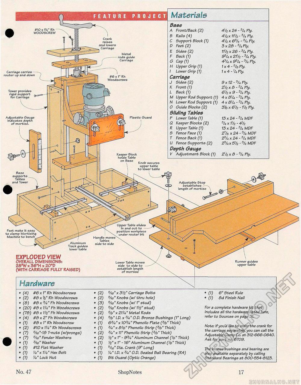
Adjustable Stop establishes -— length of mortise ^ Upper Table slides in and out to — position workpiece under router bit Handle moves Tables side to side Aluminum Track guides lower table FEATURE PROJECT #10 x VA" Rh WOOPSCREW Crank raises and lowers Carriage
• (1) 6" Steel Rule • (1) 3d Finish Nail For a complete hardware kit that includes all the hardware listed here, refer to Sources on page 31. Note: If you'd like to order the crank for the carriage separately, you can call the Adjustable Clamp Co. at 312-666-0640. Ask for part no. 6709. The bronze bushings and bearing are also available separately by calling Standard bearings at 300-554-3123. Hardware Feet make it easy to clamp Mortising Machine to bench EXPLODEP VIEW overall dimensions: 26,!w * 36nh x 20"D (with carriage fully raised) Lower Table moves side to side to -establish length of mortise Runner guides upper table fMaterials 3aee A Front/Sack (2) 41/2 x 24 - 3/4 Fly. 3 Rails (4) 41/2 x 111/2 - 5/4 Ply. C Support Slock (1) 41/2 x 63U - % Ply. D Feet (2) 3x28~3/4Ply. E Sides (2) 11V2 x 26 - 3/4 Ply. F Sack (1) &>/4 x 21% - 3/4 Ply. G Cap (1) 4?JU x 93/4 - 3/4 Ply. H Upper Grip (1) 1x4-5/& Ply. I Lower Grip (1) 1x4-% Ply. Carriage J Sides (2) 9x12- 3/4 Ply. K Front (1) 21/2 x 3-3/4 Ply. L Sack (1) 61/2 x 9 - 3U Ply. M Upper Rod Support (1) 4 x &/4 - 3/4 Ply. N Lower Rod Support (1) 4 x 31/4 - 3/4 Ply. 0 Guide Slocks (2) 3% x 61/2 -11/2 Ply. Sliding Tables P Lower Table (1) 13x24- 3/4 MPF Q Keeper Slocks (2) 3/4 x P/2 - 41/2 R Upper Table (1) 13x24- 3I4 MPF S Fence Face (1) 2% x 24 - 3/4 MPF T Fence Sack (1) 23/4 x 24 - 3/4 MPF U Fence Supports (2) 23/4x5</2 - 3U MPF Depth Gauge V Adjustment Slock (1) 21/2 x3-3/4 Ply. #6 x 1" Rh Woodscrews Plastic Guard Carriage carries -router up and down ) Tower provides rigid support ta-co--for Carriage Adjustable Gauge indicates depth of mortise. Base and Tower Metal rods guide Carriage Keeper Block holds Table on Base Knob secures upper table to lower table No. 47 ShopNotes 17 |


