49 - Cabinet Maker's Tool Chest, страница 29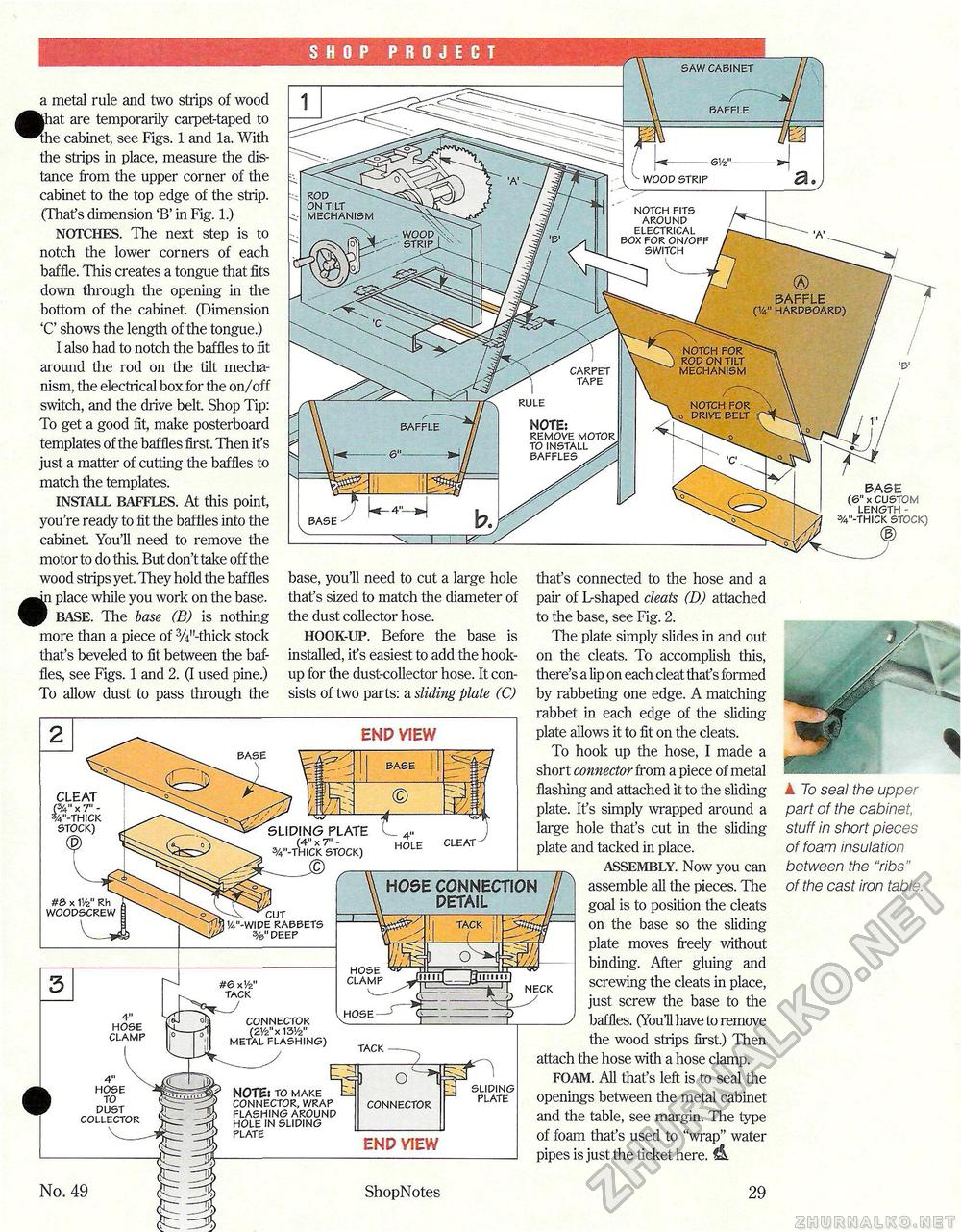
SHOP PROJECT saw cabinet a metal rule and two strips of wood |hat. are temporarily carpet-taped to The cabinet, see Figs. 1 and la. With the strips in place, measure the distance from the upper corner of the cabinet to the top edge of the strip. (That's dimension 'B' in Fig. 1.) NOTCHES. The next step is to notch the lower corners of each baffle. This creates a tongue that fits down through the opening in the bottom of the cabinet. (Dimension 'C' shows the length of the tongue.) I also had to notch the baffles to fit around the rod on the tilt mechanism, the electrical box for the on/off switch, and the drive belt. Shop Tip: To get a good fit, make posterboard templates of the baffles first. Then it's just a matter of cutting the baffles to match the templates. INSTALL BAFFLES. At this point, you're ready to fit the baffles into the cabinet. You'll need to remove the motor to do this. But don't take off the wood ships yet They hold the baffles an place while you work on the base. f BASE. The base (B) is nothing more than a piece of 3/4ILthick stock that's beveled to fit between the baffles, see Figs. 1 and 2. (I used pine.) To allow dust to pass through the wood strip rod on tilt mechanism notch fits around electrical box for on/off switch wood, • strip ixx BAFFLE (v hardboard) notch for rod on tilt mechanism carpet tape rule notch for drive belt NOTE: remove motor to install ^ baffles . BASE (6" x CUSTOM length -%"-thick STOCK) base, you'll need to cut a large hole that's sized to match the diameter of the dust collector hose. HOOK-UP. Before the base is installed, it's easiest to add the hookup for the dust-collector hose. It consists of two parts: a sliding plate (C) that's connected to the hose and a pair of L-shaped cleats (D) attached to the base, see Fig. 2. The plate simply slides in and out on the cleats. To accomplish this, there's a lip on each cleat thafs formed by rabbeting one edge. A matching rabbet in each edge of the sliding plate allows it to fit on the cleats. To hook up the hose, I made a short connector from a piece of metal flashing and attached it to the sliding plate. It's simply wrapped around a large hole that's cut in the sliding plate and tacked in place. ASSEMBLY. Now you can assemble all the pieces. The goal is to position the cleats on the base so the sliding plate moves freely without binding. After gluing and neck screwing the cleats in place, just screw the base to the _y baffles. (YouH have to remove the wood strips first.) Then attach the hose with a hose clamp. FOAM. All that's left is to seal the openings between the metal cabinet and the table, see margin. The type of foam that's used to "wrap" water pipes is just the ticket here. & CLEAT p/4" x 7" -%"-thick stock) SLIDING PLATE I (4" x T -3/4"-thick stock) hole cleat HOSE CONNECTION DETAIL #e> X V/z" Rh WOODSCREW cut v4"-wide rabbets 3/&" deep tack hose clamp #6 xVz' tack connector (2Yz" x 13'/2" metal flashing) hose clamp tack sliding plate hose to dust collector NOTE: to make connector, wrap flashing around hole in sliding plate connector A To seal the upper part of the cabinet, stuff in short pieces of foam insulation between the "ribs" of the cast iron table. No. 49 ShopNotes 29 |


