49 - Cabinet Maker's Tool Chest, страница 8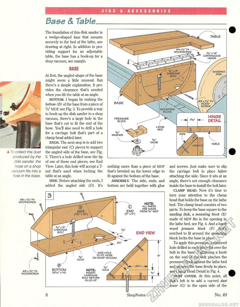
JIGS & ACCESSORIES 3aee & Table. A To collect the dust produced by the disk sander, the hose on a shop vacuum fits into a hole in the base. The foundation of this disk sander is a wedge-shaped base that mounts securely to the bed of the lathe, see drawing at right. In addition to providing support for an adjustable table, the base has a hook-up for a shop vacuum, see margin. BASE At first, the angled shape of the base might seem a little unusual. But there's a simple explanation. It provides the clearance that's needed when you tilt the table at an angle. BOTTOM. I began by making the bottom (B) of the base from a piece of MDF, see Fig. 3. To provide a way to hook up the disk sander to a shop vacuum, there's a large hole in the base that's cut to fit the end of the hose. You'll also need to drill a hole for a carriage bolt that's part of a clamp head added later. ENDS. The next step is to add two triangular end (Q pieces to support the angled side of the base, see Fig. 3. There's a hole drilled near the tip of one of these end pieces, see End View. Later, this hole will accept a T-nut that's used when locking the table at an angle. SIDE. Before attaching the ends, I added the angled side (D). It's nothing more than a piece of MDF that's beveled on the lower edge to fit against the bottom of the base. ASSEMBLY. The side, ends, and bottom are held together with glue and screws. Just make sure to slip the carriage bolt in place before attaching the side. Since it sits at an angle, there's not enough clearance inside the base to install the bolt later. CLAMP HEAD. Now it's time to turn your attention to the clamp head that holds the base on the lathe bed. The clamp head consists of two parts. To keep the base square to the sanding disk, a mounting block (E) made of MDF fits in the opening in the lathe bed, see Fig. 4. And a hardwood pressure block (F) that's notched to fit around the mounting block locks the base in place. To apply this pressure, a centered hole drilled in each piece fits over the bolt in the base. Tightening a knob on the end of the bolt pinches the pressure block against the lathe bed and secures the base firmly in place, see Clamp Head Detail in Fig. 4. DUST COVER. At this point, all that's left is to add a curved dust cover (G) to the open side of the No. 49 #0 x 1'/2" Fh woodscrew ShopNotes #© x V/z" Fh woodscrew BOTTOM (6'/i6M x 14) V/z" BHD VIEW NOTE: all parts are made from 3/4" mdf NOTE: hole insert carriage bolt before glue-up hole size hole to fit hose on shop vacuum |


