49 - Cabinet Maker's Tool Chest, страница 10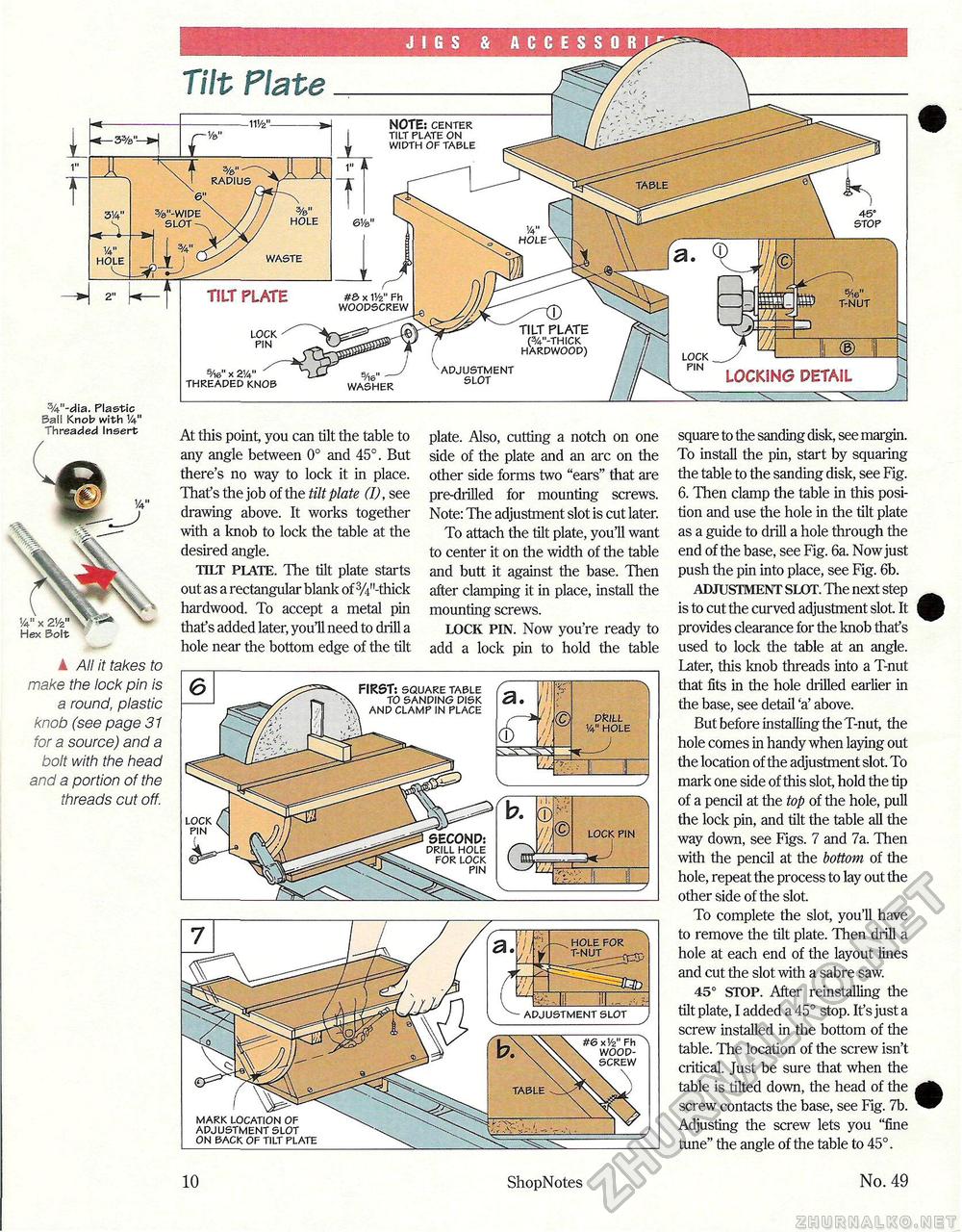
10 ShopNotes No. 49 JIGS & ACCESSOR! NOTE: center tilt plate on width of table radius table %"-wide slot- hole HOLE waste hole TILT PLATE #S> x 1V2" Fh woodscrew TILT PLATE (%"-thick hardwood) lock pin lock pin adjustment slot 5/i6"x2y4" threaded knob LOCKING DETAIL S/16" — washer %"-dia. Plastic Ball Knob with V* Threaded Insert square to the sanding disk, see margin. To install the pin, start by squaring the table to the sanding disk, see Fig. 6. Then clamp the table in this position and use the hole in the tilt plate as a guide to drill a hole through the end of the base, see Fig. 6a. Now just push the pin into place, see Fig. 6b. ADJUSTMENT SLOT. The next step is to cut the curved adjustment slot. It provides clearance for the knob thafs used to lock the table at an angle. Later, this knob threads into a T-nut that fits in the hole drilled earlier in the base, see detail 'a' above. But before installing the T-nut, the hole comes in handy when laying out the location of the adjustment slot. To mark one side of this slot, hold the tip of a pencil at the top of the hole, pull the lock pin, and tilt the table all the way down, see Figs. 7 and 7a. Then with the pencil at the bottom of the hole, repeat the process to lay out the other side of the slot. To complete the slot, you'll have to remove the tilt plate. Then drill a hole at each end of the layout lines and cut the slot with a sabre saw. 45° STOP. After reinstalling the tilt plate, I added a 45° stop. It's just a screw installed in the bottom of the table. The location of the screw isn't critical. Just be sure that when the table is tilted down, the head of the screw contacts the base, see Fig. 7b. Adjusting the screw lets you "fine tune" the angle of the table to 45°. At this point, you can tilt the table to any angle between 0° and 45°. But there's no way to lock it in place. That's the job of the tilt plate (I), see drawing above. It works together with a knob to lock the table at the desired angle. TILT PLATE. The tilt plate starts out as a rectangular blank of 3/i"-thick hardwood. To accept a metal pin that's added later, you'll need to drill a hole near the bottom edge of the tilt plate. Also, cutting a notch on one side of the plate and an arc on the other side forms two "ears" that are pre-drilled for mounting screws. Note: The adjustment slot is cut later. To attach the tilt plate, you'll want to center it on the width of the table and butt it against the base. Then after clamping it in place, install the mounting screws. LOCK PIN. Now you're ready to add a lock pin to hold the table ▲ All it takes to make the lock pin is a round, plastic knob (see page 31 for a source) and a bolt with the head and a portion of the threads cut off. FIRST: square table to sanding disk , and clamp in place pfejll 1/4" hole lock pin LOCK PfN SECOND: drill hole for lock \ pin hole for T-NUT_r adjustment slot #& x V2" Fh . wood-\ screw table mark location of adjustment slot on back of tilt plate |


