57 - A Shop-Built Pin Router, страница 15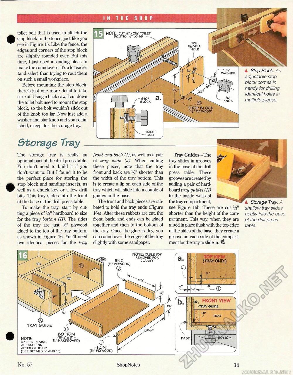
! N THE SHOP toilet bolt that is used to attach the stop block to the fence, just like you see in Figure 15. Like the fence, the edges and corners of the stop block are slightly rounded over. But this time, I just used a sanding block to make the roundovers. It's a lot easier (and safer) than trying to rout them on such a small workpiece. Before mounting the stop block, there's just one more detail to take care of. Using a hack saw, I cut down the toilet bolt used to mount the stop block, so the bolt wouldn't stick out of the knob too far. Now just add a washer and star knob and you're finished, except for the storage tray. Storage Trayk Stop Block. An adjustable stop block comes in handy for drilling identical holes in multiple pieces. The storage tray is really an optional part of the drill press table. You don't need to build it if you don't want to. But I found it to be the perfect place for storing the stop block and sanding inserts, as well as a chuck key or a few drill bits. This tray slides into the front of the base of the drill press table. To make the tray, start by cutting a piece of V4" hardboard to size for the tray bottom (H). The sides of the tray are just V2" plywood glued to the top of the tray bottom, as shown in Figure 16. You'll need two identical pieces for the tray front and back (I), as well as a pair of tray ends (J). When cutting these pieces, note that the tray front and back are V2" shorter than the width of the tray bottom. This is to create a lip on each side of the tray which will slide into a couple of guides in the base. The front and back pieces are rabbeted to hold the tray ends (Figure 16a). After these rabbets are cut, the front, back, and ends can be glued together and then to the bottom of the tray. Once the glue is dry, you can round over the edges of the tray slightly with some sandpaper. Tray Guides -The ^ tray slides in grooves in the base of the drill press table. These grooves are created by adding a pair of hard-board tray guides (K) to the inside walls of the tray compartment, see Figure 16b. These are cut V4" shorter than the height of the compartment. This way, when they are glued in place flush with the top edge of the sides of the base, they create a groove on each side of the compartment for the tray to slide in. iL k Storage Tray. A shallow tray slides neatly into the base of the drill press table. ■•\Vz" TOP VIEW (TRAY ONLY) FRONT VIEW^ GUIDE TRAY END ('/a" PLYWOOD) Q> NOTE: TABLE TOP REMOVED FOR CLARITY FRONT O/2" PLYWOOD) ® TRAY GUIDE NOTE: !4" LIP REMAINS AT EACH END AFTER GLUE-UP (SEE DETAILS 'a' BOTTOM (V7/,e" X 6" - 1/4" HARDBOARD) No. 57 ShopNotes 15 |


