57 - A Shop-Built Pin Router, страница 20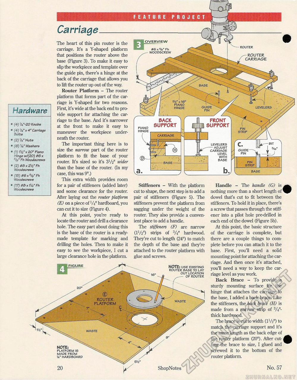
Hardware • (4) %"-20 Knobs • (4) %"x4" Carriage Bolt s • (2) V4" Nuts • (6) 1/4" Washers • (1) 1V2" x 20" Piano Hinge w/(20) #6 x %" Fh Woodscrews • (2) m x 2V2" Fh Woodscrews • (15) #6 x %" Fh Woodscrews • (17) #8 x 1%" Fh Woodscrews 11/2" x 16' piano hinge guide pin FEATURE PROJECT Carriage The heart of this pin router is the carriage. It's a Y-shaped platform that positions the router above the base (Figure 3). To make it easy to slip the workpiece and template over the guide pin, there's a hinge at the back of the carriage that allows you to lift the router up out of the way. Router Platform - The router platform that forms part of the carriage is Y-shaped for two reasons. First, it's wide at the back end to provide support for attaching the carriage to the base. And it's narrower at the front to make it easy to maneuver the workpiece underneath the router. The important thing here is to size the narrow part of the router platform to fit the base of your router. Ifs sized so it's 3V2" wider than the base of the router. (In my case, this was 9".) This extra width provides room for a pair of stiffeners (added later) and some clearance for the router. After laying out the router platform (E) on a piece of W hardboard, you can cut it to size (Figure 4). At this point, you're ready to locate the router and drill a clearance hole. The easy part about doing this is the base of the router is a ready-made template for marking and drilling the holes. Then to make it easy to see the workpiece, I cut a large clearance hole in the platform. OVERVIEW router #6 x %" Fh woodscrew ROUTER CARRIAGE PACK SUPPORT FRONT SUPPORT piano hinge strip carriage en levelers — adjust carriage level with base guide pin pin strip base base Stiffeners - With the platform cut to shape, the next step is to add a pair of stiffeners (Figure 5). The stiffeners prevent the platform from sagging under the weight of the router. They also provide a convenient place to add a handle. The stiffeners (F) are narrow (IV2") strips of V4" hardwood. They're cut to length (24") to match the depth of the base and they're attached to the router platform with glue and screws. Handle - The handle (G) is nothing more than a short length of * dowel thafs cut to fit between the stiffeners. To hold it in place, there's a screw that passes through the stiff-ener into a pilot hole pre-drilled in each end of the dowel (Figure 5b). At this point, the basic structure of the carriage is complete, but there are a couple things to complete before you can attach it to the base. First, you'll need a solid mounting point for attaching the carriage. And then once it's attached, you'll need a way to keep the carriage level as you work. Back Brace - To provide a sturdy mounting surface for the hinge that attaches the carriage to the base, I added a back brace. Like the stiffeners, the back brace (H) is made from a narrow strip of V4"-thick hardwood. The brace is cut to width (IV2") to match the carriage support and it's the same length as the back edge of the router platform (20"). After cut-ting the brace to size, I glued and screwed it to the bottom of the router platform. FIGURE NOTE: use existing router base to lay out location of router NOTE: platform is made from 1/4" hardboard 5Vz" 20 ShopNotes No. 57 |


