57 - A Shop-Built Pin Router, страница 21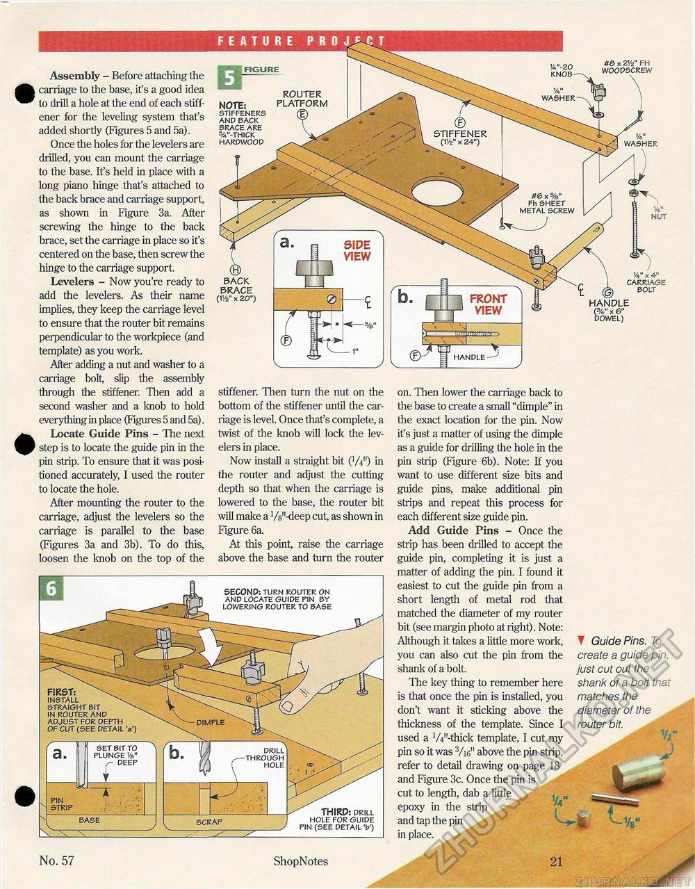
Assembly - Before attaching the carriage to the base, it's a good idea to drill a hole at the end of each stiff-ener for the leveling system that's added shortly (Figures 5 and 5a). Once the holes for the levelers are drilled, you can mount the carriage to the base. It's held in place with a long piano hinge that's attached to the back brace and carriage support, as shown in Figure 3a. After screwing the hinge to the back brace, set the carriage in place so it's centered on the base, then screw the hinge to the carriage support. Levelers - Now you're ready to add the levelers. As their name implies, they keep the carriage level to ensure that the router bit remains perpendicular to the workpiece (and template) as you work. After adding a nut and washer to a carriage bolt, slip the assembly through the stiffener. Then add a second washer and a knob to hold everything in place (Figures 5 and 5a). Locate Guide Pins - The next step is to locate the guide pin in the pin strip. To ensure that it was positioned accurately, I used the router to locate the hole. After mounting the router to the carriage, adjust the levelers so the carriage is parallel to the base (Figures 3a and 3b). To do this, loosen the knob on the top of the FIGURE BACK BRACE (11/2" x 2O") 1/4" x 4" CARRIAGE BOLT HANDLE X 6" DOWEL) stiffener. Then turn the nut on the bottom of the stiffener until the carriage is level. Once thaf s complete, a twist of the knob will lock the levelers in place. Now install a straight bit (W) in the router and adjust the cutting depth so that when the carriage is lowered to the base, the router bit will make a W'-deep cut, as shown in Figure 6a. At this point, raise the carriage above the base and turn the router on. Then lower the carriage back to the base to create a small "dimple" in the exact location for the pin. Now it's just a matter of using the dimple as a guide for drilling the hole in the pin strip (Figure 6b). Note: If you want to use different size bits and guide pins, make additional pin strips and repeat this process for each different size guide pin. Add Guide Pins - Once the strip has been drilled to accept the guide pin, completing it is just a matter of adding the pin. I found it easiest to cut the guide pin from a short length of metal rod that matched the diameter of my router bit (see margin photo at right). Note: Although it takes a little more work, you can also cut the pin from the shank of a bolt. The key thing to remember here is that once the pin is installed, you don't want it sticking above the thickness of the template. Since I used a W'-thick template, I cut my pin so it was 3/i6n above the pin strip, refer to detail drawing on page 18 and Figure 3c. Once the pin is cut to length, dab a little y H epoxy in the strip and tap the pin in place. ▼ Guide Pins. To create a guide pin, just cut out the shank of a bolt that matches the diameter of the router bit. No. 57 ShopNotes 21 |


