62 - Box Joint Jig, страница 26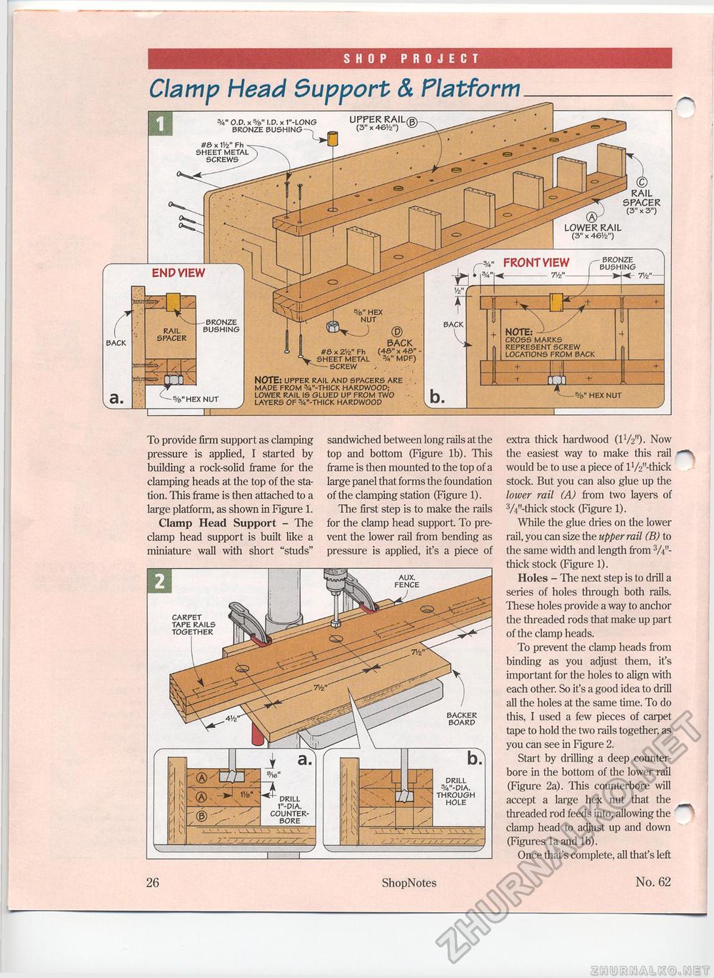
SHOP PROJECT Clamp Head Support & Platform BACK NOTE: CROSS MARKS REPRESENT SCREW LOCATIONS FROM BACK NOTE: UPPER RAIL AND SPACERS ARE MADE FROM V-THICK HARDWOOD; LOWER RAIL IS GLUED UP FROM TWO LAYERS OF %"-THICK HARDWOOD %" HEX NUT To provide firm support as clamping pressure is applied, I started by building a rock-solid frame for the clamping heads at the top of the station. This frame is then attached to a large platform, as shown in Figure 1. Clamp Head Support - The clamp head support is built like a miniature wall with short "studs" sandwiched between long rails at the top and bottom (Figure lb). This frame is then mounted to the top of a large panel that forms the foundation of the clamping station (Figure 1). The first step is to make the rails for the clamp head support To prevent the lower rail from bending as pressure is applied, ifs a piece of extra thick hardwood (1W1)- Now the easiest way to make this rail would be to use a piece of lV2"-thick stock. But you can also glue up the lower rail (A) from two layers of 3A"-thick stock (Figure 1). While the glue dries on the lower rail, you can size the upper rail (B) to the same width and length from 3/V'-thick stock (Figure 1). Holes - The next step is to drill a series of holes through both rails. These holes provide a way to anchor the threaded rods that make up part of the clamp heads. To prevent the clamp heads from binding as you adjust them, it's important for the holes to align with each other. So it's a good idea to drill all the holes at the same time. To do this, I used a few pieces of carpet tape to hold the two rails together, as you can see in Figure 2. Start by drilling a deep counter-bore in the bottom of the lower rail (Figure 2a). This counterbore will accept a large hex nut that the threaded rod feeds into, allowing the clamp head to adjust up and down (Figures la and lb). Once that's complete, all that's left 26 ShopNotes No. 62 |


